Marel Test Process
Preface
The goal of this document is to help in the usage of MarelTestProcess application.
Introduction
MarelTestProcess is an application for testing components and semi-finished products.
Interface
The following image is the main window of the application:
Following sections describe in detail all main window components.
Menu and toolbar
All the functions foreseen by the testing program are accessible from the menu and can be selected with the mouse.
The following table shows all the buttons present in the toolbar with the relative function:
Users
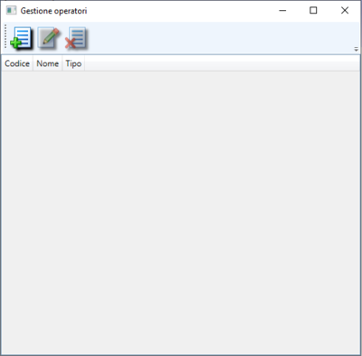
To open the user management panel, click ![]() and access this window :
and access this window :
Craete new user
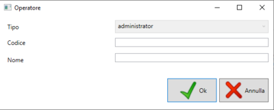
To create a new user click on ![]() and fill in the fields proposed in the following window :
and fill in the fields proposed in the following window :
Fill in the required fields and click OK to confirm creation :
- Type : choose between administrator or standard user
- Code : enter a code for the operator ( max. 10 characters)
- Name : type the user's name
Edit user
To modify a user select it from the list and then on the icon ![]() and you will be taken to the same user creation screen, with the exception that the fields codice, nome they will not be shown. Select the field to change and press OK to confirm the changes.
and you will be taken to the same user creation screen, with the exception that the fields codice, nome they will not be shown. Select the field to change and press OK to confirm the changes.
Delete user
To delete a user, select the desired user and then click on the icon ![]() and confirm the operation by clicking on OK.
and confirm the operation by clicking on OK.
Login
Once the program has been started, to access the functions it will be necessary to log in by pressing the button  and we will access this screen :
If it is the user's first login, just write the code and press enter, otherwise enter the set code and password.
Logout
Models
To configure a model or type of product that you want to test, click on ![]() to access this screen :
to access this screen :
The window is divided into two panels, the left panel for managing models, the right panel for adding or deleting parts.
New model
To create a new model, click on ![]() to access the following screen :
to access the following screen :
Fill in the fields with the required information
- Model : Enter the model of the component to be tested
- Description : Enter a description of the device
- Product code : Enter the product code
- Operational code : Enter an operational code
- Family : Select the family to associate to the product
Edit model
To modify a model in the list, you need to select one and click on the button ![]() . The same model creation screen will open except that the fields are all filled with the model data. Change the fields you want to press OK , and confirm saving on the next screen.
. The same model creation screen will open except that the fields are all filled with the model data. Change the fields you want to press OK , and confirm saving on the next screen.
Copy model
To copy a model already inserted, you need to select the model you want to copy and click on the button ![]() . The window that appears is the same as in the creation except that the fields are already filled in. It is necessary to change the code and the product code if you want to save the copy, as there cannot be identical product codes or codes. If you write an identical code present in another model or a product code present in another model, a warning message will appear that will prevent the saving.
. The window that appears is the same as in the creation except that the fields are already filled in. It is necessary to change the code and the product code if you want to save the copy, as there cannot be identical product codes or codes. If you write an identical code present in another model or a product code present in another model, a warning message will appear that will prevent the saving.
Delete model
To delete an inserted template, it is necessary to select one and click on the button ![]() , and confirm the deletion by pressing OK on the next screen.
, and confirm the deletion by pressing OK on the next screen.
Parts configuration
For each model you can add parts, previously configured using the buttons found in the panel on the right.
Add parts
To add a new part in the selected model, it is necessary to select the type from the drop-down menu next to Type of parts and then select the desired part from the drop-down menu next to Type and press add ![]() .
.
Delete parts
To delete an inserted part, select it, and click on the delete button ![]() and confirm the deletion by clicking on OK in the following warning message.
and confirm the deletion by clicking on OK in the following warning message.
Parts types
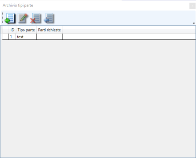
To configure the parts you must first configure the type by clicking ![]() and select Advanced → Part type configuration from the drop-down menu and the following screen will open:
and select Advanced → Part type configuration from the drop-down menu and the following screen will open:
New type parts
To create a new part type it is necessary to click ![]() to access the following screen:
to access the following screen:
Enter the name in the Part type field and click OK to complete the saving
Edit part type
To modify a part type inserted just click ![]() and the same screen will open as when creating a new one, with the Part type field already filled in. Edit the field and press OK to confirm the change or Cancel to cancel the change.
and the same screen will open as when creating a new one, with the Part type field already filled in. Edit the field and press OK to confirm the change or Cancel to cancel the change.
Delete part type
To delete a type of part it is necessary to select it and click on ![]() and confirm the deletion by clicking on OK on the next screen. It is not a real elimination, but the selected type will be marked as eliminated so it will no longer be possible to associate it with any model until this status is changed.
and confirm the deletion by clicking on OK on the next screen. It is not a real elimination, but the selected type will be marked as eliminated so it will no longer be possible to associate it with any model until this status is changed.
Undo delete
To change the status of deleted to a type of part it is necessary to select that type and click on ![]() and confirm by clicking OK in the next message. Once the deleted status has been removed, it will be possible to use this type again to be associated with the configured models.
and confirm by clicking OK in the next message. Once the deleted status has been removed, it will be possible to use this type again to be associated with the configured models.
Parts
Create new type
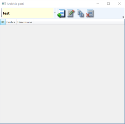
To create a new type it is necessary to select a type of parts from the list, as we saw in the previous paragraph, and click on the new button ![]() to access this screen:
to access this screen:
Fill in the required fields:
- Description : Enter a description for the part you are adding
Complete the creation by clicking on OK .
Edit type
To modify an entered type, select it and press the edit key ![]() to access the same screen as when creating a new one, but with the code and description fields already compiled. Change the fields you want and proceed with saving by clicking on OK.
to access the same screen as when creating a new one, but with the code and description fields already compiled. Change the fields you want and proceed with saving by clicking on OK.
Copy type
To copy an entered type, select it and press the copy key ![]() to access the same screen as when creating a new one, but with the description field already filled in. Enter the new code and proceed with saving by clicking OK.
to access the same screen as when creating a new one, but with the description field already filled in. Enter the new code and proceed with saving by clicking OK.
Delete type
To delete an entered type, select it and press the delete key ![]() and confirm the deletion by clicking on OK at the next warning message.
and confirm the deletion by clicking on OK at the next warning message.
Family
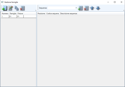
To be able to configure a family, click on the button ![]() to access this screen:
to access this screen:
The window is divided into two panels, the one on the left is used to create a new family while the one on the right is used to associate a sequence to that particular family.
Create family
To create a family click on the button ![]() and fill in the fields on the following screen:
and fill in the fields on the following screen:
The fields to be filled in are these :
- Family : enter a name for the new family
- Fixture : enter a name for the fixture associated with the family
Edit family
To modify a family that has already been created just select it and click on ![]() , it will open the same screen as when creating a new one. Modify the desired fields press OK and confirm the modification for saving.
, it will open the same screen as when creating a new one. Modify the desired fields press OK and confirm the modification for saving.
Copy family
To copy a family just select it and click on ![]() , change the family field and press OK to confirm the copy.
, change the family field and press OK to confirm the copy.
Delete family
To delete a family it is necessary to select it and then click on the button ![]() press OK and confirm the deletion on the next screen.
press OK and confirm the deletion on the next screen.
Add a sequence
To add a sequence to the family, it is necessary to select the previously created sequence via the drop-down menu next to the Sequence  in the second panel press
 ![]() to add the sequence. If, on the other hand, you want to delete a previously added sequence, you must select it and press the delete button
to add the sequence. If, on the other hand, you want to delete a previously added sequence, you must select it and press the delete button ![]() and always from the second panel confirm the deletion by pressing OK .
and always from the second panel confirm the deletion by pressing OK .
The sequence will appear in the box below. In order to manage the order if more sequences have been added, use the appropriate buttons ![]() and
and ![]() .
.
Select the sequence you want to move and click ![]() if you want to move it one step below or
if you want to move it one step below or ![]() if you want to move it one step above.
if you want to move it one step above.
Shift data/Production lot
In order to start testing the components or semi-finished products it is necessary to set the lot to be tested. To do this, click on the Shift Data icon ![]() to access the following screen:
to access the following screen:
In this screen we should select the product code to be tested using the drop-down menu available. It is necessary to enter the date of the lot under test, if it is not entered manually, the date of the current day will be automatically set. If additional parts have been configured in the selected model, they will be listed in the center panel. In this case it is also possible to add an identification number and a date for each part of the model. To do this, you need to select with the mouse the part we want to update with the new data and in the number , date and supplier fields enter the correct information and press the Update button to confirm. Once you have entered the required data, confirm the lot by pressing OK .
If the lot changes, you will need to close the current batch and reopen a new one. To do this, click on the Lot ![]() icon and click Restart to update the information for the new lot, otherwise Close lot and the window will close and then have to reopen it and update the data.
icon and click Restart to update the information for the new lot, otherwise Close lot and the window will close and then have to reopen it and update the data.
Test
The term Test identifies a phase of acquisition and storage of the values read on one or more inputs. The software provides the possibility to store the tests locally in its own archive.
Diagnostic Test
The diagnostic test is simply a sequence of commands created by the administrator operator to test the correct operation of the software and of all devices connected to the machine that must be used during testing. This test must be performed periodically, every 24 hours, to check if there are defects in the devices, if it is not launched it will not be possible to perform any other kind of tests . Even if the diagnostic test has been performed, the operator will be able to run it again manually if necessary.
New test
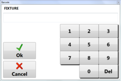
Select New Test or press the button ![]() .In the case of the first test of the batch or from the start of the application, the software requires that the code of the fixture or fixing template of the product be entered to verify that the test bench is ready:
.In the case of the first test of the batch or from the start of the application, the software requires that the code of the fixture or fixing template of the product be entered to verify that the test bench is ready:
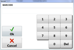
Subsequently it will be necessary to repeat the operation by pressing New Test or the button ![]() to display the window to enter the code :
to display the window to enter the code :
By clicking OK the test will start immediately.
The system is equipped with a barcode reader that automates the test start-up procedure by following the same logic; initially the fixture code must be read only once and then only the code of the piece to be tested.
Reading the product barcode ensures that the model of the piece corresponds to that of the specified lot and is also necessary to associate the serial number with the test results.
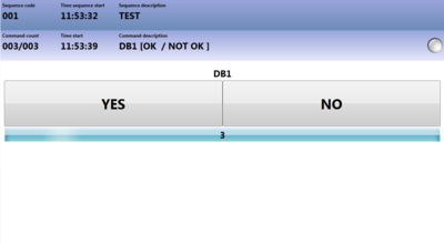
The commands in progress will be displayed in the central panel of the main screen of the program and with a specific command, an operator confirmation may also be requested:
At the end of the test, in the event of a negative result, the following options will be displayed:
The options are:
- Retry : test restarts from the first command of the block
- Confirm NOK : the test is interrupted and saved in the archive
- Discard : test is interrupted but not saved in the archive
Start test
To start the test, press the start button ![]() ,and test will start.
,and test will start.
Pause test
During the testing phase it is possible to pause the program by pressing the button  . The program will pause until the operator presses it again. Without any loss of data or validity of the test.
Stop test
Commands
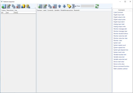
To access the list of commands, just click on the sequences icon ![]() to access the following screen :
to access the following screen :
The panel is divided into three columns, the first for creating sequences, the second displays the list of commands in the sequence, and the third is the list of commands that can be added to the list.
Sequence
In the first column you can add a new sequence using the appropriate buttons :
| Button | Function |
|---|---|
| | Create new sequence |
| | Edit selected sequence |
| | Copy selected sequence |
| | Delete selected sequence |
| | Import sequence from text file |
| | Export selected sequence to text file |
When creating a new sequence, you will need to specify :
- Code : Sequence identification code
- Description : Description of the sequence
- Log : Select the flag if you want to automatically save the log file at the end of each sequence
Edit
Copy
Select a sequence, click on ![]() for the related commands. In the new window displayed enter the code, the description and set the log mode as for the creation of a new sequence.
for the related commands. In the new window displayed enter the code, the description and set the log mode as for the creation of a new sequence.
Delete
To delete a sequence, simply select it, click ![]() and confirm the deletion of the sequence.
and confirm the deletion of the sequence.
Import sequence
Import a sequence from a text file created with the sequence export function. Click on ![]() and select the file to import.
and select the file to import.
Export sequence
Export the selected sequence to a text file. Click on ![]() and save the file by selecting the destination folder.
and save the file by selecting the destination folder.
Commands management
In the panel on the right you can see the list of commands available to add.
To add a new instruction or command, select the insertion point (previous command among those inserted) then drag it with the mouse from the list on the right. Enter the parameters, depending on the command, and press the Ok key to confirm the addition.
To copy a command, select it and choose ![]() . Change the parameters if necessary and press OK .
. Change the parameters if necessary and press OK .
To edit a command, select it and choose ![]() . Change the parameters if necessary and press OK .
. Change the parameters if necessary and press OK .
To delete a command, select it and choose ![]() . Answer Yes to the next confirmation message.
. Answer Yes to the next confirmation message.
To move a command, select it and choose ![]() to move it one step up or
to move it one step up or ![]() to move it one step below.
to move it one step below.
To move the label of a command it is necessary to select the command where the label is present and then click ![]() , the button while it is active, it will only move the labels present in the commands using the directional arrows. Once the movement has been completed, click again
, the button while it is active, it will only move the labels present in the commands using the directional arrows. Once the movement has been completed, click again ![]() to disable the label movement of the command. When the option is active, an easy-to-recognize blue square will appear around the key.
to disable the label movement of the command. When the option is active, an easy-to-recognize blue square will appear around the key.
To move a command block, select the commands you want to move and click ![]() , then click with the mouse on the command where you want to move the block.
Example: We have this sequence of commands
, then click with the mouse on the command where you want to move the block.
Example: We have this sequence of commands
Selecting the commands we want to move with the mouse and then clicking on the button to move the block
The commands will be temporarily copied until we click again in the part of the sequence where we want them to be pasted, in the example we have clicked on the TESTBLOCCO5 command
The selected commands TESTBLOCCO2,TESTBLOCCO3,TESTBLOCCO4 are thus moved immediately after TESTBLOCCO5.
In the Find field you can write what you want to search for in the sequence and press ![]() to update the search. Any command that matches the search will be highlighted in green. Delete the text and press refresh to reset the search.
to update the search. Any command that matches the search will be highlighted in green. Delete the text and press refresh to reset the search.
By selecting a command or commands, pressing the right mouse button, you can change the execution type of the command or commands, or rename the variables of the same. To modify the execution click on Type of execution and select which of the three types you want, to modify the variable select Modify Parameters and select rename variable and write the new name in the text field.
Commands parameters
Each command includes a series of fixed parameters, always present, and a series of variable parameters required or not depending on the command. This paragraph summarizes the fixed ones, while for the variable ones they will be listed in the paragraph concerning the description of the commands themselves.
Number
Indicates the position where the command will be placed in the sequence. The parameter is automatically calculated when adding the command based on the selected position.
Description
Possible description to be associated with the command for easier reading. If left blank, the program sets it automatically.
Command
Selected command that cannot be changed once the entry has been confirmed.
Label
The label can be used in the other commands to identify the point at which the sequence continues in the case of tests on returned values or in the case of cyclic operations.
Variable
For some commands it is used as the destination of the captured result, for others as a parameter to be displayed. When used as a read value target, if it already exists, the previous value is overwritten. Variables starting with # are also saved in the database as single entities of values returned from testing.
Command execution mode
Normal : the command is executed normally;
Exclude : the command even if it is present in the sequence is ignored;
Execute always : the command is normally executed when reached according to the sequence or executed even in the event of an error in the testing sequence. This mode can be useful for resetting the drives at the end of the sequence in the event of an interruption.
List of available commands
This paragraph summarizes all the implemented commands that can be used in the implementation of the testing sequence. For each command the use of the “variable” parameter is specified and the other expected are listed.
Code comment / Commento: Adds a null command that can be used for easier reading of the sequence or as the target of a condition or cycle.
| Parameter | Description |
|---|---|
| Variable | not used |
Digital input read / Lettura input digitale: Reads the value of the digital input.
| Parameter | Description |
|---|---|
| Variable | Destination of the read value |
| Input channel | Digital input channel to be acquired |
| Result value | True if checked, False otherwise |
| NOT OK Break | If selected, the execution of the sequence stops with negative results in the event that the value read does not correspond to the Result value |
| OK Jump to | If set, when the read value corresponds to Result value the sequence continues to the command identified with the Label , skipping a series of instructions |
| Break Message | Warning message for the operator in case of NOT OK |
Digital output write / Scrittura output digitale: Writes the status of the digital output.
| Parameter | Description |
|---|---|
| Variable | not used |
| Output channel | Digital channel to write |
| Value | If selected, it closes the contact, otherwise it opens it |
Digital output pulse / Impulso output digitale: Generates a pulse on a digital output.
| Parameter | Description |
|---|---|
| Variable | not used |
| Output channel | Digital channel to write |
| Time | Pulse duration in milliseconds |
Digital input alarm / Allarme input digitale: reads a digital input until the status change or at the end of the command block
| Parameter | Description |
|---|---|
| Variable | Destination of the read value |
| Input channel | Digital input channel to be read |
| Result value | True if checked, False otherwise. The alarm is triggered when the read value differs from the specified value |
| Warning message | Warning message for the operator in the event of an alarm |
| End block | Label that identifies the command at which the check is disabled |
| Output channel | Digital output channel to write in case of activated alarm |
| Output value | Value to write to the specified output channel. Select to close the contact, vice versa to open it |
Analog input read / Lettura input analogico: reads an analog input.
| Parameter | Description |
|---|---|
| Variable | Destination of the read value |
| Input channel | Analog input channel to be acquired |
| Minimum value | Minimum acceptable value for comparison |
| Maximum value | Maximum acceptable value for comparison |
| NOT OK Break | If selected, the execution of the sequence stops with negative results if the value read is not included between the minimum value and maximum value |
| OK Jump to | If set, when the read value corresponds to Result value the sequence continues to the command identified with the Label , skipping a series of instructions |
| Ok if not match | Reverses the logic of the return value check. The command will have a positive result if it is not included in the range |
| Break Message | Warning message for the operator in case of NOT OK |
Analog output write / Scrittura output analogico: writes the status of the analog output.
| Parameter | Description |
|---|---|
| Variable | not used |
| Output analog channel | Analog output channel to write |
| Value | Value to set according to the type of analogue output |
Monitor message add / Aggiungi messaggio video: adds a line on the screen with a message for the operator.
| Parameter | Description |
|---|---|
| Variable | variable used in displaying the message |
| Operator message text | Enter the text to be displayed. If a variable is specified, the value of the variable is displayed to the right of the message |
| Variable value formatting | Indicates the formatting of the variable {0} is default. To display a decimal number use the format {0.0} with many 0s after the point according to the decimals |
Monitor message clear / Rimuovi messaggi video: removes one or more displayed messages.
| Parameter | Description |
|---|---|
| Variable | not used |
| Delete all messages | If selected, it deletes all messages previously added with the monitor message add command. Otherwise only the last added |
Monitor double buttons / Doppio bottone monitor: Inserts a warning message with a duration established by operator choice between OK or NOT OK.
| Parameter | Description |
|---|---|
| Variable | result of selection |
| Operator message text | Message to be displayed for the operator |
| Text button OK | Insert the text of the OK button. Ex: Ok, Confirm, Next etc .. |
| Text button NOT OK | Enter the text of the NOT OK button. Ex: No, Cancel etc .. |
| Time (seconds) | Time available to the operator to select between OK or NOT OK. Enter 0 to disable the timeout |
| OK input | To also enable the choice via digital input, select the channel to be associated with the positive confirmation |
| KO input | To also enable the choice via digital input, select the channel to be associated with the negative confirmation |
Monitor value bar add / Barra valore a video: It inserts a bar to visualize the value of a variable graphically as well as numerically.
| Parameter | Description |
|---|---|
| Variable | variabile utilizzata nella visualizzazione del valore |
| Minimum value | Minimum value highlighted for graphical representation |
| Maximum value | Maximum value highlighted for graphical representation |
| Variable value formatting | Indicates the formatting of the variable {0} is default. To display a decimal number use the format {0.0} with many 0s after the point according to the decimals |
Monitor value bar clear / Rimuovi barra valore: Removes one or more graphical display bars of values.
| Parameter | Description |
|---|---|
| Variable | not used |
| Delete all messages | If selected, it deletes all the bars previously added with the monitor value bar add command. Otherwise only the latest added |
Monitor clear / Pulisci monitor: cleans the entire area intended for the execution of the sequence.
| Parameter | Description |
|---|---|
| Variable | not used |
Monitor camera add / Aggiunge riquadro immagine camera: adds a frame for viewing the image acquired by the camera.
| Parameter | Description |
|---|---|
| Variable | not used |
| Operator message text | Enter the text to be displayed above the box. |
Monitor camera clear / Rimuovi riquadro immagine camera: removes the inserted camera frame.
| Parameter | Description |
|---|---|
| Variable | not used |
System wait / Sistema attesa: waits for the specified time.
| Parameter | Description |
|---|---|
| Variable | not used |
| Time | Time available to the operator to select OK or NOT OK expressed in milliseconds |
| OK input | Digital input channel for OK confirmation |
| KO input | Digital input channel for NOT OK confirmation |
System repeat count / Sistema ripeti contatore : repeats the commands included in the specified block n times up to the End of Block parameter
| Parameter | Description |
|---|---|
| Variable | outcome of the cycle whether completed or not |
| Repeat counter | Number of block repetitions |
| End block | Indicates the end of the block containing the commands to be repeated |
System repeat time / Sistema ripeti tempo: repeats the commands included in the specified block n times up to the End of Block parameter. Once the time has elapsed, it always exits the cycle after executing the last command of the block.
| Parameter | Description |
|---|---|
| Variable | outcome of the cycle whether completed or not |
| Time (seconds) | Duration of the cycle |
| End block | Indicates the end of the block containing the commands to be repeated |
System get elapsed time / Ottieni tempo trascorso
| Parameter | Description |
|---|---|
| Variable | variable to which time is assigned |
| Command label | Label that identifies the command from which to calculate the elapsed time |
System insert note / Inserisci nota: enters a note during testing which will be saved in the LOG file.
| Parameter | Description |
|---|---|
| Variable | variable in which you will find the confirmation or not of the insertion of the note |
| Note type | select the note type between ResultInfo or ProcessInfo to specify the list proposed to the operator |
System wait input / Sistema attesa ingresso : waits for a maximum of the specified time or at the change of state of the digital input.
| Parameter | Description |
|---|---|
| Variable | not used |
| Time (milliseconds) | Maximum waiting time |
| Input channel | Digital input channel |
| Result value | Expected value for the input channel, if selected it waits until the contact is detected |
Variable boolean test / Test vero-falso variabile: CCheck if a given variable is true or false.
| Parameter | Description |
|---|---|
| Variable | not used |
| Variable to be tested | Select the variable you want to test |
| Result value | If selected, specifies that the variable to be tested must have a positive value |
| NOT OK Stop | If the variable test is negative, the test stops |
| OK jump to | If the variable test is positive, the sequence passes to the command identified with the selected label |
| Break message | Message to be displayed to the operator in case of failure |
Variable value test / Test valore variabile: Check that the value of the selected variable is between the minimum and maximum set in the command.
| Parameter | Description |
|---|---|
| Variable | not used |
| Variable to be tested | Select the variable you want to test |
| Minimum value | Set the minimum acceptable value |
| Maximum value | Set the maximum acceptable value |
| NOT OK Stop | If selected and the value of the variable is not between the minimum and maximum set, the test stops with an error message |
| OK jump to | If the variable test is positive, the sequence passes to the command identified with the selected label |
| Ok if not match | Reverses the logic of the return value check. The command will have a positive result if the value found is not included in the range |
| Break message | Message to be displayed to the operator in case of failure |
Variable value test and / Test valore variabile AND : executes a logical AND between the variable to be tested and the set value
| Parameter | Description |
|---|---|
| Variable | Variable to which the value returned by the function is assigned |
| Variable to be tested | Select the variable you want to test |
| Value | Value with which the logical AND will be made with the variable |
| NOT OK Stop | If selected and the result of the function is negative, the test stops with an error message |
| OK vai a | If the variable test is positive, the sequence passes to the command identified with the selected label |
| Ok if not match | Reverses the logic of the return value check. The command will have a positive result if the value found is not included in the range |
| Break message | Message to be displayed to the operator in case of failure |
Example: if the variable has a value of 3, the result will be positive if we test with a value of 2, 1 or 3.
Device read value / Lettura valore dispositivo
| Parameter | Description |
|---|---|
| Variable | Destination of the read value |
| Device input | Device channel to read |
| Minimum value | Minimum acceptable value for comparison |
| Maximum value | Maximum acceptable value for comparison |
| NOT OK Break | If selected, the execution of the sequence stops with negative results if the value read is not included between the minimum value and maximum value |
| OK Jump to | If set, when the read value corresponds to Result value the sequence continues to the command identified with the Label , skipping a series of instructions |
| Ok if not match | Reverses the logic of the return value check. The command will have a positive result if it is not included in the range |
| Break Message | Warning message for the operator in case of NOT OK |
Device write value / Scrittura valore dispositivo
| Parameter | Description |
|---|---|
| Variable | not used |
| Device input | Device channel to write |
| Value | Value to set according to the type of output |
Device command function / Funzione comando dispositivo
| Parameter | Description |
|---|---|
| Variable | Destination of the data returned by the execution of the command |
| Device command | These parameters vary according to the device to be tested and the libraries used |
| Command parameters separated by ”;” | QThese parameters vary according to the device to be tested and the libraries used |
| Values accepted | Value returned by executing the command. In case of string to take the first or the first characters insert the character * |
| Range +/- | In case the returned value is numeric, it is possible to specify the minimum and maximum range for the test |
| NOT OK Break | If selected, the execution of the sequence stops with negative results if the value read is not included between the minimum value and maximum value |
| OK Jump to | If set, when the read value corresponds to Accepted value the sequence continues to the command identified with the Label , skipping a series of instructions |
| Ok if not match | Reverses the logic of the return value check. The command will have a positive result if it is not included in the range or does not coincide with the specified value |
| Break Message | Warning message for the operator in case of NOT OK |
Math variables subtract / Sottrazione matematica di due variabili
| Parameter | Description |
|---|---|
| Variable | Destination of the data returned by the execution of the command |
| Variable to be tested | Select the variable you want to test |
| Variable to be tested | Select the variable you want to subtract from the first variable |
| Minimum value | Set the minimum acceptable value |
| Maximum value | Set the maximum acceptable value |
| NOT OK Break | If selected, the execution of the sequence stops with negative results if the subtracted value is not between the minimum value and the maximum value |
| Ok if not match | Reverses the logic of the return value check. The command will have a positive result if it is not included in the range or does not coincide with the specified value |
| Break Message | Warning message for the operator in case of NOT OK |
Operator tools
To access the operator tools click on the Operator tools button ![]() and from the drop-down menu select the operation you want to perform.
The options are as follows :
and from the drop-down menu select the operation you want to perform.
The options are as follows :
- Change Password
- Run a diagnostic test
- Run the restore sequence
- Run a test sequence
- Open backup window
- Print test label
- Software update
- Info test parameters
Change password
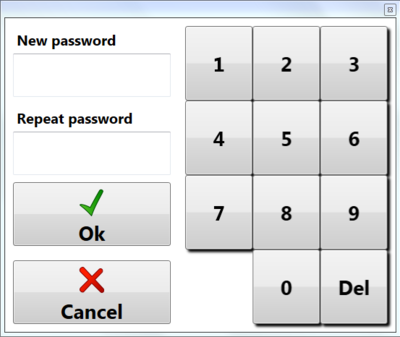
Once logged in, the password can be changed by selecting the option from Operator Tools —> Change Password and the screen is accessed:
Enter the new password in the New password field and repeat it in the Repeat password field. Click OK to confirm the change or Cancel to exit the screen.
Run a diagnostic test
The diagnostic test is performed automatically every day otherwise it is not possible to carry out component tests. In any case, the operator has the possibility to carry out a diagnostic test if he deems it necessary to verify the correct operation of the equipment.
Select Operator Tools —> Run Diagnostic Test and the diagnostic test set for the station will start.
Run the restore sequence
If defined, the restore sequence is like all the other sequences, a series of commands that allows the system to be restored from an anomalous or alarm condition. In any case, the administrator operator has the possibility to manually execute the sequence if he deems it necessary to check the correct operation of the equipment
Run a test sequence
The operator can execute a test sequence among those created by selecting Operator tools —> Execute test sequence , executes all the commands in the sequence without saving anything being a test to verify that the is correct.
Print test label
Print a test label, where the test parameters you have entered into the layout will appear. Example: # TEST.resultstring # TEST.ID # SHIFTPARTS.Supplier etc ..
Software update
Allows you to select the folder with the updated software and will install it automatically.
Test parameters info
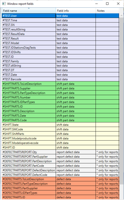
Opens the list of test parameters that can be exported or inserted in the label of the label for printing. If only for report is written in the notes, it means that in the label that field will not be replaced with the requested data but the code after the ”#” symbol will remain.
Open backup window
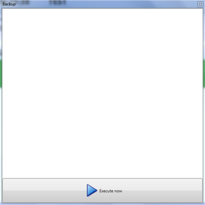
In order to perform the backup it is necessary to select Operator tools —> Open backup window and click on the Execute button as shown in the following image.
Once the database backup has been launched, we will see on the screen if it was successful or if there was an error, in which case Completed or Not performed will appear at the end of the messages in the central panel.
Archive
Use this function to load a test previously stored in the application archive.
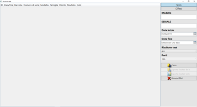
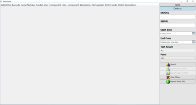
* Select Archive from the menu or press the ![]() to access the following window:
to access the following window:
- Press the Search button to view the list of archived tests;
- Then select the one to export and press the Export results button after completing the excel form for export.
Tests can also be searched based on the following information :
- Date (from/to)
- Model
- Serial
In the date field you can specify the search start and end period, in the remaining fields just enter the characters to search for.
Defects
By clicking on defects you will access the screen of the parts resulting defective during the various tests.
Export
To export the tests it is necessary to create an Excel file and fill the first row of the Excel sheet with the names for the columns of the data to be displayed and the underlying row with the #. codes. The information to be exported can be easily found by clicking on Report fields info and the list of test information will open:
If the description of the report only field is present, it means that it can only be used for reports.
Once you have checked the data you want to export, open the excel file and insert the Field name in the excel cell. The first row is recommended to be used to name the column with a description of the information displayed. Below is an example of how the file should be created:
Notes
This tool displays a window with the list of notes entered. In the process it is possible to add a command that displays the “ProcessInfo” type notes among which the operator must select one to continue with the test . Those of the “ResultInfo” type are instead displayed at the end of the test in the event of a negative result for the selection of any defect found.
Create note
To create a new note click on the button ![]() and the following screen will open:
and the following screen will open:
Fill in the form with the requested information:
- Code : Enter the code for the note, once entered it cannot be changed
- Description : Enter the description of the note
- Type : Select what type of note it is, ResultInfo or ProcessInfo
Edit note
To edit a note, select it and click ![]() , the same screen will open as when creating a new one, only with the fields already filled out in the open note. Change the fields you want and click OK to save.
, the same screen will open as when creating a new one, only with the fields already filled out in the open note. Change the fields you want and click OK to save.
Copy note
To copy a note it is necessary to select it and click ![]() , he same screen will open as when creating a new one, only with the description and type fields already set. All that remains is to enter the required code and click OK to save.
, he same screen will open as when creating a new one, only with the description and type fields already set. All that remains is to enter the required code and click OK to save.
Delete note
To delete a note it is necessary to select and click ![]() and confirm by clicking OK on the message that will appear immediately after.
and confirm by clicking OK on the message that will appear immediately after.
Stations
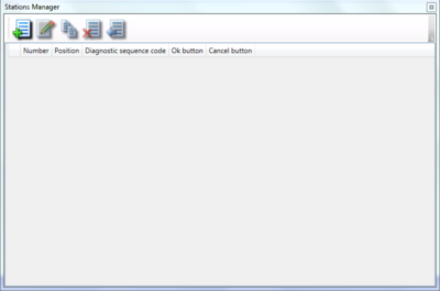
To create a station it is necessary to click on ![]() Advanced → Station configuration to access the following screen:
Advanced → Station configuration to access the following screen:
Create station
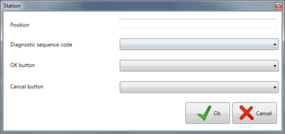
To create a new station click on the new button![]() and enter the required data in the following screen:
and enter the required data in the following screen:
Enter the required information:
- Position: Write the location of the station or a description to recognize it
- Diagnostic test sequence: Select the diagnostic test sequence from the drop-down menu
- Restore test sequence: Select the restore system sequence from the drop-down menu
- Button OK: Select the channel you want to use for the OK button
- Button cancel: Select the channel you want to use for the Cancel button
Finally press OK to add the station.
Edit station
To modify a previously created station, select it and click on the edit button ![]() and in the panel that will open, identical to that of the creation of the station, modify the fields you want and confirm the modification by pressing OK .
and in the panel that will open, identical to that of the creation of the station, modify the fields you want and confirm the modification by pressing OK .
Copy station
To copy a station it is necessary to select it and click on the copy button ![]() . If desired, before confirming the operation by pressing the OK key, changes can be made to the station fields.
. If desired, before confirming the operation by pressing the OK key, changes can be made to the station fields.
Delete station
To delete a station it is necessary to select it and click on the delete button ![]() and confirm by pressing OK on the next screen. It is not a real elimination, but a state, in which the station can no longer be used as long as it is in the elimination state.
and confirm by pressing OK on the next screen. It is not a real elimination, but a state, in which the station can no longer be used as long as it is in the elimination state.
Undo deletion station
To cancel the deletion status of a station, it is necessary to select the station and press the button ![]() and confirm the operation by pressing OK .
and confirm the operation by pressing OK .
Channels
Before starting the test, it is necessary to define the channels to be used.
To be able to define them you will need to click ![]() and select Advanced → Channel configurations from the drop-down menu to access the following screen:
and select Advanced → Channel configurations from the drop-down menu to access the following screen:
Create new channel
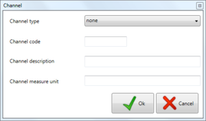
To create the channel you will need to specify the following information
- Type : select the type of channel you are configuring from the drop-down menu, DO, DI, AO, AI, DEVOUT, DEVIN, CUSTOM, ND
- Code : write the channel code,there cannot be two identical channels
- Description : enter a description of the channel if necessary
- Measure unit : enter the unit of measure if necessary
Edit channel
To modify the channel it will be necessary to select the channel and then click on the button ![]() . The screen displayed will be the same as the creation with only the fields already filled in with the data of the selected channel, and here you will have the possibility to modify the channel.
. The screen displayed will be the same as the creation with only the fields already filled in with the data of the selected channel, and here you will have the possibility to modify the channel.
Copy channel
To copy the channel just select the channel you want to copy and click on the button ![]() . The screen displayed will be the same as the creation with the fields already filled in excluding Code since there cannot be two channels with the same code
. The screen displayed will be the same as the creation with the fields already filled in excluding Code since there cannot be two channels with the same code
Delete channel
To delete a channel that has already been set, it will be necessary to select it and then click the button ![]() and confirm the deletion of it.
and confirm the deletion of it.
Station channels
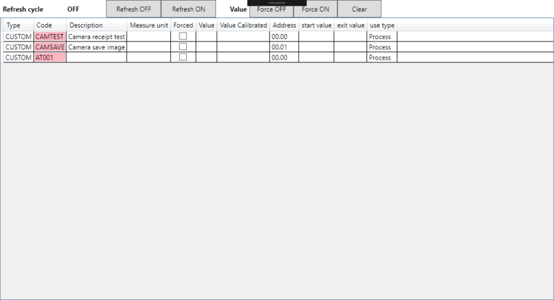
It is accessed from the ![]() menu by selecting Advanced → Station channel configurations . The panel is used only for the first system setup.
menu by selecting Advanced → Station channel configurations . The panel is used only for the first system setup.
Channels window
Refresh ON : enable timer to update input channels
Refresh OFF : disable timer to update input channels
Force OFF : reset selected digital output channel leaving it in forced state
Force ON : set selected digital output channel leaving it in forced state
Clear : release the forced state
Camera recipe manager
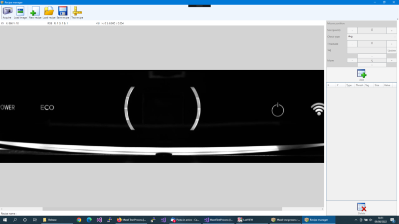
To use the commands related to the analysis of defects via camera, it is necessary to define at least one test recipe. By recipe we mean a list of areas of interest in which the software determines whether the LED is on or off based on the brightness of the acquired photo.
Click on Configuration ![]() and select from dropdown menu Advanced –> Camera recipe manager to access the following screen :
and select from dropdown menu Advanced –> Camera recipe manager to access the following screen :
The following keys are shown in the window toolbar:
Preliminary operations for creating / modifying recipe
Select the image with the ![]() key or start a test sequence and interrupt the sequence with the Pause key (in the main application window)
key or start a test sequence and interrupt the sequence with the Pause key (in the main application window)  then capture the image with the
 ![]() key.
key.
After loading the source image, proceed with the creation of a new recipe or load one of those previously saved as described in the following paragraphs.
New recipe
Edit recipe
Press the ![]() key to load the recipe to be modified. The name of the loaded recipe is displayed in the lower bar of the window.
key to load the recipe to be modified. The name of the loaded recipe is displayed in the lower bar of the window.
Management of verification areas
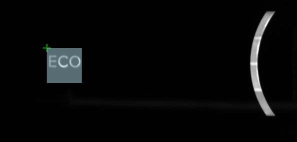
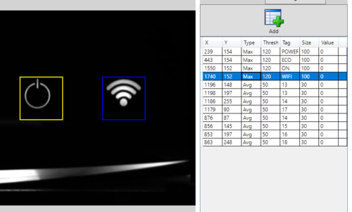
To insert a new area, click with the mouse in the upper left corner of the point of interest:
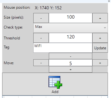
in the right panel, if necessary, modify the various parameters of the point and confirm the insertion with the ![]() key.
key.
To delete the inserted area, after selecting it:
For each area can be defined: size, type of verification, threshold, and tags that can be modified from the right panel:
Size (pixels) : indicates the size of the square;
Check type : check type selectable between Max or Avg. In the first case the software checks that the brightest point in the defined area is greater than the set threshold, in the second case it checks that the average value of the points is higher than the threshold.
Threshold : lower limit for positive outcome;
Tag : tag assigned to the element (for easier analysis of the results). Confirm the tag with the Update button.;
The defined areas can be moved with the keys +/- to the right of the text Move.
At any time, by pressing the ![]() key, the software checks the result of all the areas entered, indicating them with
key, the software checks the result of all the areas entered, indicating them with ![]() in the event of a positive result or
in the event of a positive result or ![]() in case of failure. The edges of the area itself are colored green or red according to the result.
in case of failure. The edges of the area itself are colored green or red according to the result.


