GasTapsEvoTestSystem
This manual describes the procedures for the proper use of the software GasTapsEvoTestSystem supplied with the taps test system .
Taps test system
This system has been designed and developed for the acquisition of values of torque, pressure, leakage and temperature of the taps during the rotation in the two directions: anticlockwise and clockwise.
During the testing phase the torque curves detected are plotted and are saved components with peak values over a maximum threshold set. The system can also automatically perform leak testing of valves and magnets .
The system is equipped with a second engine for each position which can adjust the advancement speed and thrust force during axial movement.
For each slot, the system is further equipped with four digital inputs for reading as many contacts during the phases of handling.
Settings and configuration
This chapter describes how to install and configure the program and acquisition of all components and drivers necessary.
Application configuration
During the installation automatically creates the configuration file GasTapsEvoTestSystem.exe.config with the correct settings. however if you need to make some changes (customer name, serial communication etc …) you can open the file with any text editor such as Windows Word Pad.
The content of the file is as follows:
<?xml version="1.0" encoding="utf-8"?>
<configuration>
	<startup>
		<supportedRuntime version="v4.0" sku=".NETFramework,Version=v4.5" />
	</startup>
	<appSettings>
		<!--lingua utilizzata nell'applicazione:it,es,en-->
		<add key="LINGUA" value="it"></add>
		<!--seriale di comunicazione con forno/camera climatica (""=non collegato)-->
		<add key="COMM_FORNO" value=""></add>
		<!--tipo forno-->
                <add key="TIPO_FORNO" value="1"></add>
		<!--indirizzo ip del forno/camera climatica (""=non collegato)-->
		<add key="IP_ADDRESS_FORNO" value="192.168."></add>
		<!--seriale di comunicazione con le PM500 (""=non collegate "1,2,3,4 ..."=per singola postazione)-->
                <add key="COMM_PM500" value="4,5,6,7,8,9,10,11"></add>
                <!--seriale di comunicazione con il modulo ingressi termocoppie e digital output se previsto (""=non collegato tipi:ADAM_4018,ICPDAS_7018Z)-->
                <add key="COMM_MODULI" value="1"></add>
                <!--modulo ingressi termocoppie (p,tttt:ADAM_4018,ICPDAS_7018Z. ""=non collegato)-->
                <add key="TIPO_MODULO_TC" value=""></add>
                <!--movimantazione assiale-->
		<add key="MOVIMENTAZIONE_ASSIALE" value=""></add>
                <!--flag per abilitazione movimentazione motorizzata-->
                <add key="MOVIMENTAZIONE_MOTORIZZATA" value ="1"/>
		<!--1=abilita la lettura degli ingressi-->
		<add key="INGRESSI_ABILITATI" value="1"></add>
		<!--generalità del cliente e nome sistema-->
		<add key="CLIENTE" value="MAREL"></add>
		<add key="SISTEMA" value="GAS TAPS EVO TEST SYSTEM"></add>
		<!--1=abilita la lettura della pressione (ulteriore ingresso Analogico per ogni rubinetto)-->
		<add key="PRESSIONE_ABILITATA" value="1"></add>
		<!--posizione prima postazione("DX" o "SX")-->
		<add key="POSIZIONE_PRIMA_POSTAZIONE" value="SX"></add>
		<!--presenza braccetto apertura porta-->
		<add key="APERTURA_FORNO" value="1" />
                <!--secondi impiegati nella movimentazione della porta-->
                <add key="TEMPO_APERTURA_FORNO" value="12" />
                <!--presenza ventola supplementare di raffreddamento-->
                <add key="VENTOLA_FORNO" value="1" />
                <!--presenza resistenza supplementare di riscaldamento-->
                <add key="RESISTENZA_FORNO" value="1" />
                <!--seriale di comunicazione e tipo dispositivo di prova della tenuta-->
                <add key="COMM_TIPO_MODULO_TENUTA" value="2,ATEQModbus"/>
                <!--controllo rotazione massima nello stesso senso-->
                <add key="ROTAZIONE_360" value="0" />
                <!--seriale di comunicazione con alimentatore di corrente variabile-->
                <add key="COMM_TIPO_ALIMENTATORE_CORRENTE" value="3,AGILENT" />
                <!--valore della singola resistenza per il comando magnete on-->
                <add key="VALORE_RESISTENZA" value="10,9" />
                <!--valore della resistenza cavo per il comando magnete on-->
                <add key="VALORE_RESISTENZA_CAVO" value="0.33" />
                <!--percorso della funzione di backup completa (programma e dati)-->
                <add key="PATH_BACKUP_COMPLETO" value="D:\backup\gastapsevotestsystem"/>
	</appSettings>
</configuration>
Starting the program
o start the application, select the command Start » Programs » MAREL » GasTapsEvoTestSystem or double-click on the desktop icon GasTapsEvoTestSystem .
Select language
In the menu , select File » Language and then click with the mouse in the corresponding to the desired language:
“it” =italian, “sp”=spanish , “en”=english etc…
he selected language will be activated on the next restart of the application.
Close application
Select File » Exit from the menu or ALT + F4 or simply the following button in the toolbar:
click on Yes button or press ENTER to the next confirmation message.
User interface
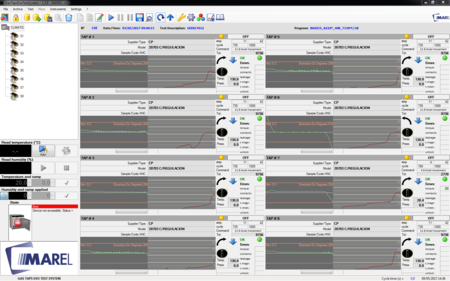
Main screen is as follows:
The top bar displays the title of the application and contains three buttons for resizing and closing the program (refer to the operating system installed on your computer).
Are located immediately below the Menu bar and Toolbar.
On the left there is the List of places and testing and Panel of the oven.
Depending on your selection in the list of places, in the center of main screen will be displayed the Panel of the place or theGraphic area.
The status bar placed in the bottom of the window, displays the current date and time without necessarily show the standard application bar of windows.
Menu bar
From the menu bar you can access all the functions provided by the test program. These functions can be selected with the mouse or keyboard, press the Alt key and then the underlined letter of the command chosen. The most-used can also be activated via a function key or a key combination as shown in the next menu.
The following table summarizes all the menu commands:
| Commands Menu | Description | Shortcut |
|---|---|---|
| File | ||
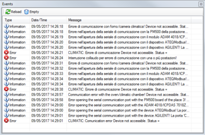
| –> Events | See the list of recorded events | CTRL + L |
| –> Advanced tool | Add more option in the tool tab | |
| –> Language | View the list of available language | |
| –> Exit | Close the application | ALT + F4 |
| Archive | ||
| –> Components | View the components Database | F2 |
| –> Advanced programs | View the advanced programs Database | F3 |
| –> Tests | View the tests Database | F9 |
| –> External tests | View the list of tests stored in another location or unit | ALT + F9 |
| –> Close | Closes an open test from the archive | CTRL + C |
| –> Backup | Start the backup utility of tests | |
| Test | ||
| –> New | Create a new test | CTRL + N |
| –> Repeat | Start a new test with the same settings as the last executed | CTRL + R |
| –> Modify | Change the setting of a test | CTRL + M |
| –> Start | Start / Resume a test | F5 |
| –> Suspend | Suspend a test | F6 |
| –> Suspend and unlock | Suspend a test and unlocks motors | |
| –> Delete | Delete a test | |
| –> Save | Save a test in the Database | |
| –> Details | View details of the program of the selected place | CTRL + D |
| –> Value max | Displays the maximum values diagram | CTRL + V |
| –> Leakage test | Display a window with the list of leakage tests performed | CTRL + T |
| –> Tests leakage/rotation | Display a window with the list of leakage/rotation tests performed | CTRL + P |
| –> Release tests | Display a window with the list of release tests performed | CTRL + S |
| –> Contact tests | Display a window with the list of contact tests performed | CTRL + X |
| –> Analysis | Display a panel for the quick access to the leakage, rotation, leakage/rotation ,release, contact tests and flow/rotation. | F7 |
| –> Result | Displays the window for entering / editing a possible result | CTRL + E |
| Place | ||
| –> Save and continue | Save the data of the place and continues testing with the remaining | |
| –> Exclude and continue | Deletes data of the place and continues testing with the remaining | |
| –> Restore tests | Restore the tests stopped | |
| Instruments | ||
| –> Install components | Opens the panel for manual management of places | F8 |
| –> Input calibrator | If Advanced option is selected, it opens the panel to calibrate the pressure and temperature inputs | |
| –> Calibration and Diagnosis | If Advanced option is selected , it opens a panel to calibrate hardware inputs | |
| –> Test digital output | If Advanced option is selected , it opens a panel to test each single digital output | |
| –> System configuration | If Advanced option is selected , it opens a panel to configure the system WARNING | |
| –> Password | Enable / Disable functions administrator, password protected | |
| –> Backup Complete | Backup the folder containing executable, settings and data | |
| Settings | ||
| –> Drawing | View / Edit graph settings | F10 |
| –> Option | Opens the settings panel program | F11 |
Toolbar
The toolbar contains buttons for quick access to some of the menu commands::
List of places and tests
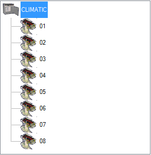
The tree list displays the oven and its places. Selecting the oven, the program displays the Panel places, instead selecting a place displays its data with the list of acquired curves and graph acquisition eventually selected Graphic Area.
Any other tests reopened from the archive are appended and are represented by a different image:
Oven panel
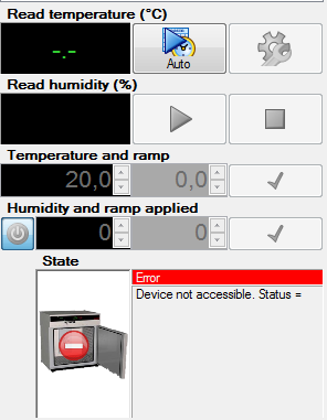
Read Temperature (°C)
Displayed the internal temperature detected by the sensor of the oven..
Read Humidity (%)
Displayed the humidity detected by the sensor of the oven.
Temperature and gradient
Indicates the temperature threshold set manually, while the gradient indicates the increase in temperature per minute. It is enabled only if manual control mode is selected.
Humidity and gradient
Indicates the humidity threshold set manually, while the gradient indicates the increase in humidity per minute. It is enabled only if manual control mode is selected.
State
It indicates the mode of operation and the status of the serial communication, accompanied by an icon corresponding :
- ONLINE–AUTO;
- ONLINE–MANUAL;
- ERROR.
If you receive the error status in the box below there is also a description explaining the problem.
To learn about the key functions go to the section Oven options. }
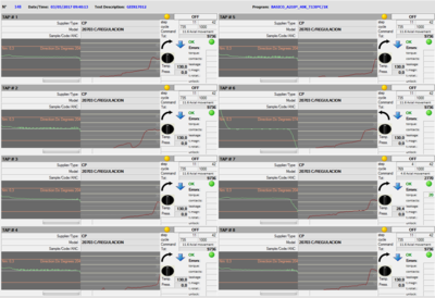
Panel places
The panel of the places provides an overview of system status while displaying all the pitches of testing:
Above, common to all places, are displayed the date / Start time testing, the test description and test program. Just below for each location the information's displayed are:
- In the top left corner there is the number for the place and to the right a colored light and a label that indicate the status as summarized in the following table:
| Status List Place | ||
|---|---|---|
 | EMPTY | Place not in testing |
 | OFF | Place with a test not in execution |
 | ON | Place with a test in execution |
 | ERR | Communication error with the hardware place |
- Just below displays the Supplier/type, model and sample / code / ANC relating to the component. Depending on the type of running program also shows the following details of the test:
- Advanced program: current step, total step, current cycle, total cycle, current command with the relative number of block and command name (Example 27.1 Oven ventilation, Block 27, command 1 name command), torque error, contacts error, leakage error, leakage/rotation error, release error and pressure out of range errors .
The colors of the number of errors will be green if below the maximum limit set. If the error counter will be higher or equal than the maximum limit set, it will be displayed with the red color.
- Lower down you see the graphic and an arrow pointing to the right or left , based on the last rotation performed. Just below ,the temperature of the detection and the pressure exerted on the component. To the right, a red icon or a green icon and labeled “OK”, “KO” indicating the presence of possible errors in the below data.
It will be displayed in green if it is within the specified tolerance, otherwise red.
Graphic Area
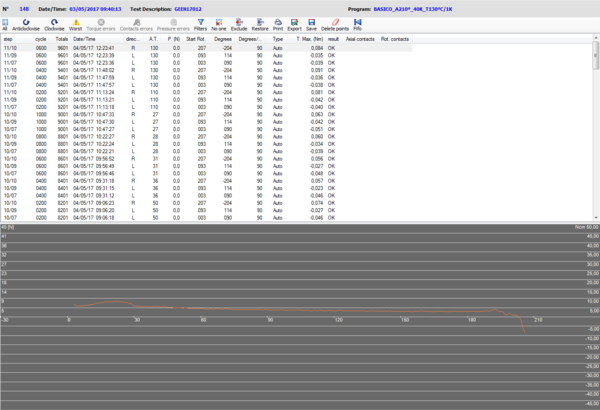
Selecting the list of test a single place, the program shows a list of the curves acquired and the graph of the measured values acquired:
In the top bar are shown the following keys depending on if in the toolbar is selected the list of pressure or rotation :
Rotation
| Tools for the Graphic Area | |
|---|---|
| | Display all the curves acquired at the same time |
| | Displays at the same time all the curves detected anticlockwise |
| | Displays at the same time all the curves detected clockwise |
| | Displays the curves with higher pick value obtained during the rotation |
| | Select the wrong curves. While pressing the SHIFT + CTRL activates the delete function curves erroneously detected |
| | Select the curves in which a contact error occurred |
| | Select the curves in which the pressure detected is out of range |
| | Show all the curves detected by the same command as the curve selected |
| | Cancel the selection of curve |
| | Exclude from the list the selected curves |
| | Restore the curves excluded from the list |
| | Print a report of the selected curves |
| | Export as a text format all the values of selected curves |
| | Save the graph displayed as image format JPEG |
| | Delete the point inserted in the graph |
| | Show all the curves acquired by the function FIFO (all the curves acquired immediately after an error curve is detected) |
In the list for each curve acquired, are show these information:
- the combination Block/Command;
- the number of the cycle refers to the step or block;
- the number of the total cycle;
- the date and the hour of the acquisition;
- direction: C clockwise rotation, A for anticlockwise rotation;
- the temperature detected at the end of the rotation movement (*);
- the pressure detected at the end of the rotation movement;
- the starting point of the rotation (expressed in degrees);
- degrees done;
- rotation speed (expressed in degrees per seconds);
- the type of curve , that can be “Auto” for the curves saved by the default settings of the test program otherwise it's empty for the curves saved for a negative result;
- torque max value (Nm);
- curve result;
- the number of detected contacts (input 1) in the axial movement;
- the number of detected contacts (input 2,3,4) in the rotation movement.
The curves with negative results, whether for exceeding the rated value in the detection of the torque or for problems in contacts, they are shown in red.
Result of the axial contacts
The column for the axial contacts show these information:
”.” = not tested;
“ok” = positive result : the state at the end of rotation meet the specified value(close or open);
“nok” = negative result : the state doesn't meet the specified value.
Result of the rotation contacts
For each contacts , can be shown these information separated by this character ”/”
”.” = not tested;
numeric value = the number of state changes, corresponds to the specified value;
numeric value between ”<” ”>” = the number of state changes, that doesn't corresponds to the specified value.
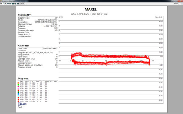
Pressure
| Tools for the Graphic Area | |
|---|---|
| | Display all the curves acquired at the same time |
| | Display at the same time all the curves acquired during the pressure movement |
| | Display at the same time all the curves acquired during the release movement |
| | Show all the curves detected by the same command as the curve selected |
| | Cancel the curve selection |
| | Delete the point inserted in the graph |
| | Print a report of the selected curves |
| | Export as text format all the values of the selected curves |
| | Save the graph displayed as image format JPEG |
In the list for each curve acquired, are show these information:
- the combination Block/Command;
- the number of the cycle refers to the step or block;
- the number of the total cycle;
- the date and the hour of the acquisition;
- direction : P for Pressure, R for Release;
- the temperature detected at the end of pressure(*);
- the pressure detected at the end of rotation;
- the starting position expressed in millimeters;
- the ending position expressed in millimeters;
- the speed of axial movement expressed in millimeter for seconds;
In the box below the list of curves, the curves for the selected test are drawn. The thrust force expressed in Newton is vertically oriented, the position scale is horizontally oriented. By clicking on the graph it's possible to draw a point in correspondence of the mouse click, that show the value of the detected force(if enabled from the graphic options, and between parentheses is show the position in millimeters). By holding the right button of the mouse , a vertical bar appear and it will show the value of the force in correspondence of the bar.
that can be connected to each location.
Test
In this section we will explain all the operations that can be performed during the test phases: start, pause, resume, modify, deleting and saving.
New
To begin the phase of rotation and acquisition of the torque we need to create a test. Select in the menu Test» New or hold the key CTRL+N; por simply, press the following button in the toolbar:
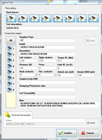
The program displays the interface for input of data relating to the test to be performed:
We have to select the places on which the testing will be performed, then press on the icons of the taps in the upper panel to enable or disable. If necessary, but not required for the purposes of test, enter a description of the test and subsequently for each component include the following information: Supplier/Type, Model, Description, Rotation Anticlockwise (degrees), Rotation Clockwise (degrees), Max torque (Nm), Pressure (N), Pressure tolerance (N), Contacts axial, Contacts rotation, Max leakage and Max and min current of release. To load data from the components archive, select all the locations listed in the list by clicking with the mouse in the column All and press Load for access to the archive:
Choose the place in the list and press Select to go back to the pane of test start. Afterwards you can manually change the setting loaded for each place simply selecting the place in the components list. The other fields : Sample/Code/ANC, Stamping/Data production, Lot/Traceability and Note they must be inserted step by step.
In the end to select the test program (unique for all components), click the panel programs Standard or Advanced and press Load for access to the selection window.
Highlight it in the list of those present in the archive and press Select. For more information on advanced program management see the relevant paragraphs in chapter Archive components and programs.
Complete the procedure by pressing Confirm or Cancel for abort the start.
Repeat
Finished a test you can start a new one with the same settings as the last program done. Select on Menu Test » Repeat or press the keys CTRL+R or, simply, press the following button on the toolbar:
As for the editing (see next paragraph), the program displays a window to enter or change any information that does not affect the operation of testing.
Modify
Also during the test we can change the information of the program that do not go to affect the implementation of the test . Choose from the menu Test » Modify, or press CTRL+M, or press this button on the toolbar:
From the window that appears you can correct the personal data of place:Supplier/Type, Model, Description, Sample/Code/ANC, Stamping / Data production, Lot/Machine and Note. Is not possible to edit: maximum torque, number of axial and rotation contacts , rotation degree (Left and Right),value of the pressure plate and relative tolerance, and the test program running. If the test is not yet started, you can also remove one or more places from it. You must press the mouse icon in the upper panel and respond Yes to the next confirmation message. The place will now be removed from the testing resulting empty.
Start
Once you created a new test you have to start it . Select fromt the menu Test » Start or press F5 or, simply, press the following button on the toolbar:
Once started the testing, at the end of each rotation, the program shows the graph of the torque detected with values of temperature and pressure detected on the component. During the leakage test phase that can be performed on a place at a time, in correspondence of the component concerned, is displayed a bar and the time left for the acquisition.
The same function can be used to resume a previously interrupted test.
Pause
If a test is paused, it suspend the acquisition of data that can be retrieved later. To pause a test you have to select the menu Test » Pause or press the F6 or, more simply, press the following button in the toolbar:
Then select Yes in the following confirmation message. Wait for the program, complete the step of moving to return the components to the position of initial zero.
Immediate break
As for the function Interruption this also stops the testing but it doesn't wait the end of the current cycle to move back the taps to start position.
To immediate break a test select the menu Test»Break and unlock or press the next button in the toolbar:
![]()
Then select Yes in the following confirmation message. Wait for the program, complete the step of moving to return the components to the position of initial zero.
Delete
The elimination of a test deletes all data. To do this you must select the menu command Test » Delete or simply press the next button in the toolbar:
Then press Yes in the following confirmation message.
Save
This function allows you to save in archive the test finished or interrupted. First, it is advisable to complete the insertion of data relating to the test and the results of test, so that once saved, it can be found easily with the research tools. Select the menu item Test » Save or, more simply, press the following button in the toolbar:
Select Yes in the following confirmation message.
Details
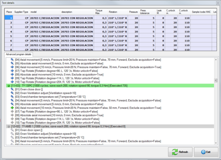
You can at any time display the details of the program test running. You must first select one of the places in the list on the right, and then select from the menu Test » Details , or press the key Ctrl + D alternatively press the following button from the toolbar:
In the window that appears summarizes all the data of the test and in the case of standard program, all steps of the running program, while in the case of advanced program, block information and controls testing.
To return to the main screen, press the Exit button.
Details advanced program
This window shows a list of blocks with the respective controls that characterize the current program. For each block next to the consecutive number (in brackets) and the name, show the number of cycles performed and the total. Immediately below lists all the commands in extended mode with the appropriate parameters enclosed in brackets. Icons to the left of each item indicate the current state of the program:
Maximum values
This function allows you to analyze for each place the maximum values of torque curves acquired during testing.
Select from the menu Test » Maximum value, or press CTRL + V to access to this window:
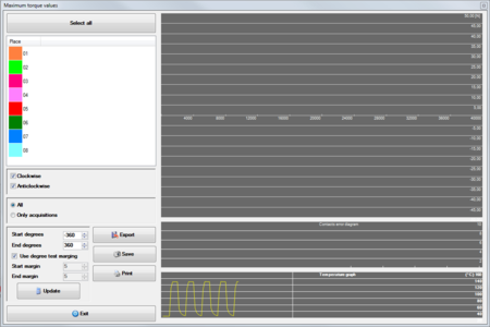
The place or places to be analyzed can be selected in the list visible in the upper left of the window itself or by pressing the button Select all. Immediately below it is necessary to activate the boxes Clockwise/Anti Clockwise to display its curves.
In form it displays three graphs and respectively starting from the top:
- graph of the maximum values;
- graph of errors in contacts;
- graph of the temperature detected in the oven
The curves displayed in the first graph are affected by the following options:
- All: graph of the maximum values of all the acquired curves also for error;
- Only acquisitions: graph of the maximum values of the curves only acquired in automatic mode.
A more detailed analysis can also be performed by changing the options for degrees that allow you to include in the calculation only a few curves or even part of them:
- Starting degrees: start value acquisition ;
- Ending degrees: end value acquisition;
- Use degrees variance: value set at the creation of test;
- Starting variance: degrees that are discarded for exclude peaks when rotation start;
- Ending variance: degrees to be discarded at the end of each curve for exclude peaks if you hit the limit.
Every time you change one of these values must be selected Update to run the calculations again. The other buttons on the form are:
- Save: save the graph of maximum values as JPEG;
- Export: export the maximum values detected as a text file ;
- Print: displays the print preview of the graphs;
- Exit: close the form.
Leakage test
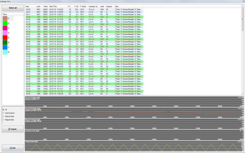
This feature show the list of the all leakage test executed during the main test. Select from the menu Test» Leakage test, or press the short key CTRL + T to access the following window:
To view the test list, select the place in the list at the top left of the window. For each test is provided the following information:
Step: information of block/command;
Cycle: cycle number of the block in execution;
Total: total cycle executed from the beginning of the test;
Date/Hour: date/hour of acquisition;
TA: Room temperature (inside the oven);
P.(N): pressure exerted on the rod of the component;
P.(mbar): test pressure exerted from the ATEQ machine;
Leakage value: value max , acquired from the machine;
Result: result assigned by the test program;
Degrees: indicate the angular position where the leakage test was performed;
Data: data read from ATEQ machine.
As shown in the previous image, the tests are listed with different coloration according to the typology. The values must be colored red in the case of a negative result.
The list can be filtered by selecting on of the following option:
- All: no filter;
- Internal leakage: Show a list of the only internal leakage tests;
- External leakage: Show a list of the only external leakage tests;
- Magnet leakage: Show a list of the only magnet leakage tests;
In the form are shown five graph and respectively starting from the top:
- graph internal leakage values : max value internal leakage;
- graph external leakage values : max value external leakage;
- graph magnet leakage values : max value magnet leakage;
- graph of errors encountered : for each negative test , the value will be incremented by a unit;
- graph of the temperature read by the oven.
In every graph , except for the temperature graph, the curves shown changes by the number of places selected.
To close the form press the button Exit.
Leakage/rotation tests
This function displays the list of all leakage/rotation test performed during the main test.
Select from the menu Test » Leakage/rotation test, or press the shortcut CTRL + P to show the following window:
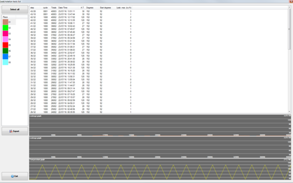
To view the list of tests, select a place from the list in the upper left of the window. For each test include the following information:
Step: information of block/command;
Cycle: cycle number of the block in execution;
Total: total cycle executed from the beginning of the test;
Date/Hour: date/hour of acquisition;
TA: Room temperature (inside the oven);
Degrees: indicate the degrees performed during the leakage test;
Starting degree: indicate the in which degree the leakage test is started;
Leakage max. (cc/h): max leakage value detected by the machine during the test;
In the graphics area for each selected component, is displayed the curve of the maximum leakage value detected during every single test executed. If you select a single acquisition, you can see graphically the leakage values acquired during rotation:
Unlock magnet test
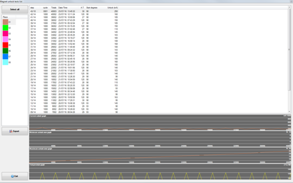
This function displays a list of all the leakage tests performed during testing. Select from the menu Test» Release test, or press CTRL + S to access this window:
To view the list of tests, select a place from the list in the upper left of the window. For each test include the following information:
Step: information of block/command;
Cycle: cycle number of the block in execution;
Total: total cycle executed from the beginning of the test;
Date/Hour: date/hour of acquisition;
TA: Room temperature (inside the oven);
Starting degree: indicate in degrees, the position where the release test is executed;
Release (mA): indicate the release value detected during the test;
Contact test
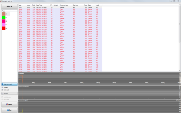
This function displays a list of all the leakage tests performed during testing. Select from the menu Test» Contact test, or press CTRL + X to access to this window:
To view the list of tests, select a place from the list in the upper left of the window. For each test include the following information:
Step: information of block/command;
Cycle: cycle number of the block in execution;
Total: total cycle executed from the beginning of the test;
Date/Hour: date/hour of acquisition;
TA: Room temperature (inside the oven);
Contact: indicate on which contact the test is executed;
Movement type: indicate the movement type executed for the test, that can be : thrust, release, clockwise rotation, anticlockwise rotation
Start Position: indicate the starting position when the test start , that can be display in millimeters or degrees , depending on the movement type
Position: Indicate after how many millimeter/degrees the state of the contact is changed
State: Indicate the contact state , that can be Open or Closed
Result: Indicate if the test result is positive OK or negative KO
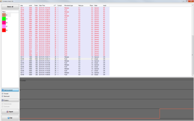
If a test is selected the graph below will appear and it will show every status changed of the contact:
Flow tests
 : immagini
This function displays the list of all flow/rotation test performed during the main test.
Select from the menu Test » Flow test, or press the shortcut CTRL + K to show the following window:
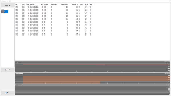
To view the list of tests, select a place from the list in the upper left of the window. For each test include the following information:
Step: information of block/command;
Cycle: cycle number of the block in execution;
Total: total cycle executed from the beginning of the test;
Date/Hour: date/hour of acquisition;
TA: Room temperature (inside the oven);
Degrees: indicate the degrees performed during the flow test;
Starting degree: indicate the in which degree the flow test is started;
Flow min. (L/hr): min flow value detected by the machine during the test;
Flow max. (L/hr): max flow value detected by the machine during the test;
Outside range %: percentage of acquired values outside first sample curve (the lastone in the list);
Max difference (L/hr): max difference from sample curve;
Result: Indicate if the test result is positive OK or negative KO
In the graphics area for each selected component, is displayed the curve of the maximum flow value detected during every single test executed and the graph of the area between max and minimum value. If you select a single acquisition, you can see graphically the flow values acquired during rotation:
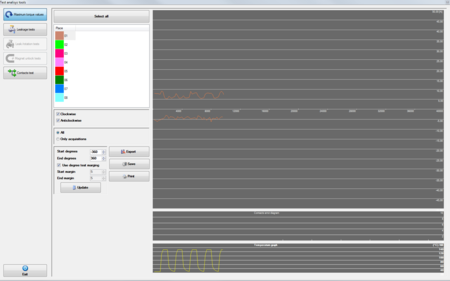
Analysis
By using this function you will access to a panel in which you will be able to analyze the result of every type of test.
Use the left-side button to view the various types of test described in the previous paragraphs.
Graphic settings
Graphic settings can be changed from the drop-down menu displayed by right-clicking in the graphics area.
Edit the scale of the cycles
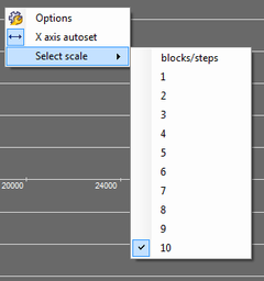
The X axis of the graph of the torque values gives the number of cycles, which can be modified in the following manner:
- click on the graph with the right mouse button;
- in the popup menu select select scale and then blocks / steps to view the subdivisions according to the blocks of the program otherwise a number from 1 to 10 representing splitter maximum number of cycles envisaged in the program:
- select autoscale to relate the lenght of X axis to the number of cycles done during the test.
Edit max value
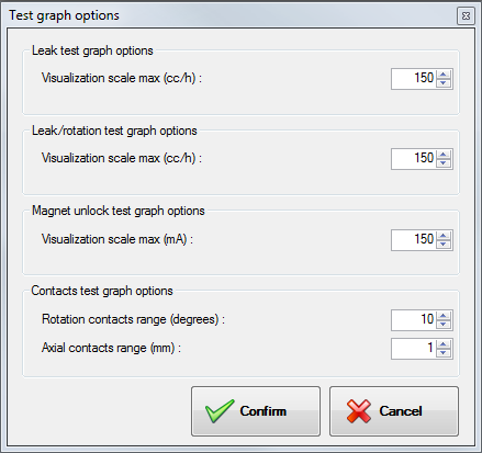
For the leakage, leakage/rotation and release graph , is possible to set the max value of the scale:
- right click with the mouse on the graph;
- by clicking on option the windows below will be shown, where you can set the max scale for the respective graphs , Leakage graph option , Leakage/rotation option, Release graph option, Flow graph option:
 : immagine
Result
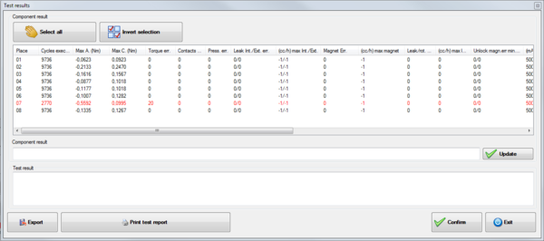
This function can access a summary window with all the data of the test and assign a result to the entire test as well and to each individual place. The results given are saved in the archive and can be included in the search functions of the tests.
Select from the menu Test » Result or press CTRL + E to access to the following window:
For each place listed in the list, shows the following information:
- Place : indicate the number of the place
- Cycles executed: total number of cycles performed (can also be less than the total expected if the place has been interrupted);
- Peak L.(Nm) : maximum value of torque counterclockwise;
- Peak R.(Nm) : maximum value of torque clockwise;
- Torque error : number of rotations in which the torque exceeded the limit;
- Contacts error : number of rotations in which was detected a problem in the contacts;
- Err. pressure : number of saved curves , in which a contact error is occurred;
- Leakage error Int./Ext. : number of internal/external leakage test failed;
- (cc/h) max Int./Ext. : max leakage values internal/external;
- Magnet error : number of magnet test failed;
- (cc/h) max magnet : max leakage value detected during the magnet test;
- Err. leakage/rotation : number of leakage error encounter during rotation;
- (cc/h) max leakage/rotation : max leakage value during the leakage/rotation tests;
- Err. magnet unlock min./max. : number of release error for minimum and maximum;
- (mA) magnet unlock min./max. : min and max values detected during the release test;
- Err. flow : number of flow test outside range (first acquired flow test is the sample);
- (L/hr) flow max./min. : min and maximum flow detected values in rotation;
- Result : result assigned by operator.
- Supplier/type : Specified in test settings;
- Model : Specified in test settings;
- Description : Specified in test settings;
- Sample/Code/ANC : Specified in test settings;
- Stamping/Production Date : Specified in test settings;
To assign at the same time to all components the same result press the button Select all, and fill the textbox Result and press the button Update. By pressing the button Invert selection is possible to select all the components that aren't selected , and deselect the one selected when the button is pressed .
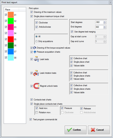
To export all displayed information, press the Export key and enter the name of the file you want to create. The data will be exported in separate text format from the tab character. Press the Confirm key to save any assigned results, or press the Print test report button to display the report, otherwise Exit to close without editing. If you press Print test report, this window will be displayed :
To view the list of tests, select a place from the list in the upper left of the window. For each test include the following information:
- Graph of max values : Print a graph depicting the torque max values of all places
- Graph of max values for each place : Print a graph depicting the torque max values of each place
- Graph of torque values detected : Print a graph depicting the curves of the torque values of all places
- Graph of pressure curves : Print a graph depicting the curves of the pressure values of all places
- Graph of leakage test : Print a graph depicting the max leakage values detected during the leakage tests
- Graph of leakage/rotation tests : Print a graph depicting the max leakage values detected during the leakage/rotation tests
- Graph of release tests : Print a graph depicting the current values detected during the release tests
- Graph of flow test: Print a graph depicting the maximum and maximum from minimum flow area values detected during the flow tests
- Graph of flow tests for single place : Print a graph depicting the maximum and maximum from minimum flow area values detected during the flow tests for every single place
- Graph of contacts tests : Print a graph of max values status change , detected during the contacts tests
- Graph of contacts tests for single place : Print a graph depicting the status change of every tested contacts for every single place
- Test program commands list : Print the list of every commands and blocks of the test
Press the Confirm key to save the settings and view the report, otherwise Cancel to close without changes and return to the test result screen.
Exclude a place
During the execution of a test you can exclude a place erasing all data acquired to continue only with the rest place. Select from the menu Places » Exclude and continue than answer YES to the next confirmation message.
Saving a place
Is possible to use this function if you want to save in archive the data from place and continue the test only with the rest of places.Select from the menu Place » Save and continue .
Test database
This chapter describes the procedures for the search and the opening of the tests that are stored locally or on an external drive (network, USB key).
Open a saved test
This feature allows you to load and view the tests previously saved in the local database. Select from the menu Archive » Test , or press F9 alternatively press the following button in the toolbar:
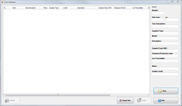
As a result the following window appears:
Pressing the button Find will display all the tests saved. You can also search by entering part of the information required in the following fields:
- Number : test number automatically assigned;
- Date from.. to .. : starting date of the test;
- Test Description;
- Supplier/type;
- Model;
- Description;
- Sample/Code/ANC:
- Stamping/Production Date;
- Lot/Traceability;
- Notes;
- Sample Result: Result assigned by the operator.
After viewing the test, select the one you want to see and press Load. The test selected will appear into the list of tests.
To permanently delete the test from the Test Database press Delete and respond YES to the following confirmation message. The delete function is only available after entering the password protection (Refer to the paragraph Password of the Tool chapter).
You can export to a text file the list of tests carried out by pressing the Export List button.
To exit this window without loading a test, press the Exit button.
Open an external test
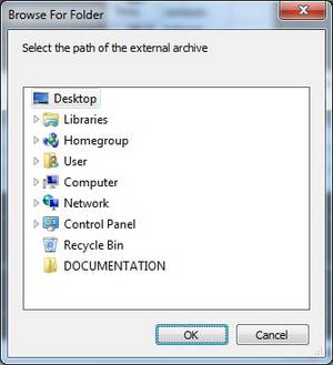
This feature allows you to load and view the tests stored on network or other external memory storage. Select from the menu “Archive»External Test” or press ALT + F9 then select the location of the archive:
If the path is valid, you will see the same window as the search and selection for testing stored locally. Then consult the previous section for more details.
Closing a test archived
This function allows you to close a test loaded from the archive and is rapresented with the following icon:
For closing the test it is necessary to select the test you want to close and select from the menu Archive » Close or press the key combination Ctrl + C ; alternatively press the following button in the toolbar:
Backup test database
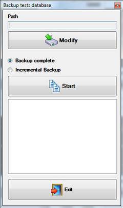
Using this feature you can make a copy of the database and all the tests stored on a network drive or external storage. Select from the menu File »Backup to access the following panel:
Opening automatically displays the last path used so you need only press the Start and wait for the completion of the copy. The backup can be of two types:
- Backup Complete: copy all the files in the destination and overwrites any files already present (with the same name so inherent to software GasTapsTestSystem);
- Incremental Backup: copy all the files that are not in the destination folder.
With the button Modify is possible to modify the path.
Archive components and programs
The paragraphs in this chapter describe the interfaces and functions for the management of the archive components of the advanced programs. While there are no special restrictions for viewing, for the management of the archives you have to enter the password as described in the first paragraph Password of tools chapter.
Components
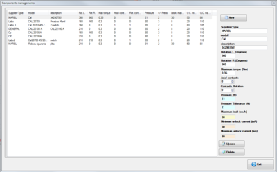
To enter the archive components select from the menu Archive » Components or press F2 ; alternatively press the following button in the toolbar:
The following window appears:
To add a component, you must:
- Press with the mouse on New button.
- Insert the various information in the fields;
- Press Update button to save data.
To edit a component, you must:
- From the list select the component to be modified.
- Modify the information displayed;
- Press Update button to save data.
To delete a component you must
- From the list select the component to be deleted.
- Press Delete button and press Yes to the next confirmation message.
To exit the window press with mouse the Exit button.
The registry component consists of the following information:
- Supplier/Type:The component manufacturer or type.
- Model:Identification code of the component.
- Description:Description if needed
- Rotation L:Specifies the maximum rotation angle of anticlockwise of the component from 0 ° to 360 °.
- Rotation R:Specifies the maximum rotation clockwise angle of the component from 0 ° to 360 °.
- Max torque:It is the maximum acceptable torque value beyond which the machine assumes that there is a failure of the component. The value is expressed in Nm (Newton / meter).
- Axial contacts:Number of contacts that can change status during the axial movement (press / release). The system can test at most one axial contact.
- Rotation counters:Number of contacts that can change status several times during the rotation phase left or right. In the system it is possible to test a maximum of three contacts of this type.
- Pressure:It indicates the nominal pressure that can be made on the component. Put 0 to disable the view and control.
- Pressure tolerance:Indicates the extent to which values the measured pressure can be considered correct.
- Max leakage(cc/h): Max leakage value acceptable during the leakage test.
- Min current for release (mA): Min current value acceptable during the magnet release test.
- Max current for release (mA): Max current value acceptable during the magnet release test.
Program
The software GasTapsEvoTestSystem provides programs for the execution of the tests: Advanced program. The advanced programs allow you to perform, in the same cycle, more rotations in different positions and also run leakage testing.
Advanced program
To enter the editor of advanced programs select menu Archive » Programs advanced or press F3 or simply press the next button in the toolbar:
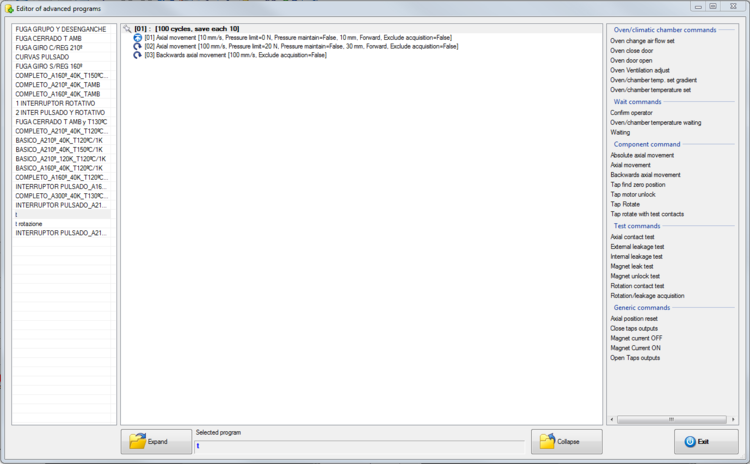
The following window appears:
The advanced programs are divided into blocks. Each block, repeated for a preset number of cycles, can contain one or more commands selectable among those in the list on the right.
The management window is divided into three panels: the left is a list of programs, the center is a list of blocks and controls belonging to the selected program, to the right the list of commands can be inserted. The panel in the center shows the list of blocks and program commands, it can be shown or as default , with every blocks and every commands , or if you press the bottom button Expand or Collapse, only the blocks.
Program
To create a new advanced program:
- Right click on the list of programs and select New from the menu that appears;
- Enter the name of the program and press OK .
To rename an advanced program:
- Right click on the program you want to rename and choose Rename from the menu that appears.
To create a copy of an existing program:
- Right click on the program you want to copy and choose Copy from the menu that appears;
- In the bottom of the list will appear an exact copy of the selected program with the same name.
To remove an advanced program:
- Right click on the program you want to delete and choose Delete from the menu that appears;
- Press Yes to the next confirmation message.
To import a new advanced program in XML format:
- Click with the right button in the program list and choose Import XML from the menu that appears;
- Enter the file name and press OK.
To export an advanced program to XML:
- Right click on the program you want to export and choose Export XML from the menu that appears;
- Enter the file name and press OK.
To print the listing of a program:
- Right click on the program and choose Print from the menu that appears;
- select the printer and press OK.
Block
To create a new block:
- Select the advanced program;
- Click with the right button of the mouse in the central list and choose New Block from the menu that appears;
- Enter a description of the block, the number of cycles, the number indicating how many cycles save a curve, and the maximum torque if other than the default component;
- Press Ok.
To edit a block:
- Click with the right button of the mouse to select the block to edit and choose Edit Block from the menu that appears;
- Edit the parameters in the following window;
- Press Ok to confirm the modifications.
To delete a block:
- Click with the right button Of the mouse to select the block to remove and select Delete block from the menu that appears;
- Press Yes to the next confirmation message.
To copy a block:
- Click with the right mouse button to select the block to be copied and choose Copy block from the menu that appears.
You can also create a link to a block. A link creates an identical copy of the selected block and any changes applied to each of the two blocks will also be applied to another. It is also possible to create more than one link for each block.
- Click with the right mouse button to select the desired block and choose Create Shortcut of this block from the menu that appears.
Command
In the right panel you can see a list of available commands to insert in the blocks.
To add a command, drag it over to the block in which you plan to add. First set if it is a command at a single execution or if it will run at each cycle of the block. Enter the parameters, depending on the command, and press OK to confirm the entry.
To edit a command, select it with the right mouse button and choose Edit command from the menu that appears. Change the parameters and press OK to confirm the changes.
To delete a command, select it with the right mouse button and choose Delete command from the menu that appears. Press Yes to the next confirmation message.
List of available commands
In this paragraph are summarized all the implemented commands that can be used in the implementation of advanced programs and are subdivide in : Oven/climatic chamber commands , Wait commands , Component command , Test commands , Generic commands.
Oven/climatic chamber commands
Oven change air flow set: Set the opening of airflap .
| Parameters | Description |
|---|---|
| AirFlap position | AirFlap positioning in percentage (0=close, 100=completely open) |
Oven door open: Open the door of the oven
Oven close door: Close the door of the oven
Oven Ventilation adjust: sets the oven/chamber ventilation fan speed
| Parameters | Description |
|---|---|
| Speed Ventilation | percentage rate of ventilation (0 = off, 100 = maximum) |
Oven/chamber temperature set: set the temperature to reach in the oven/chamber
| Parameters | Description |
|---|---|
| Temperature | set the temperature of setpoint between the range of 20 and 210 Celsius degrees |
Oven/chamber temperature set gradient: set the temperature to reach with the specified increment °C/min
| Parameters | Description |
|---|---|
| Temperature | set the temperature of setpoint between the range of 20 and 210 Celsius degrees |
| Gradient | gradient of increment higher/lower express in °C per minute |
Oven/chamber humidity set: set the humidity to reach in the oven/chamber
| Parameters | Description |
|---|---|
| Humidity | Humidity setpoint value from 0 a 100 % |
Oven/chamber humidity set gradient: set the humidity to reach with the specified increment %/min
| Parameters | Description |
|---|---|
| Humidity | Humidity setpoint value from 0 a 100 % |
| Gradient |
Wait commands
Waiting: it waits for the specified time
| Parameters | Description |
|---|---|
| Seconds | waiting time , between the range of 1 and 86400 seconds |
Long waiting: it waits for the specified time in minutes
| Parameters | Description |
|---|---|
| Minutes | waiting time , between the range of 1 and 1440 minutes |
Confirm Operator: displays a summary screen with the data of torque and the results of the leakage test carried out since the start of testing. The home screen has three buttons:
| Parameters | Description |
|---|---|
| Repeat | Reset the data in the test and restart to the first block |
| Cancel | Cancel current test and delete all the data acquired |
| Confirm | Continues with the test |
Oven temperature wait: It waits if the oven temperature is below the minimum value or if it is above the maximum value set.
| Parameters | Description |
|---|---|
| Temp. minimum | temperature minimum value |
| Temp. maximum | temperature maximum value |
Chamber humidity wait : It waits if the oven humidity is below the minimum value or if it is above the maximum value set.
| Parameters | Description |
|---|---|
| Humidity minimum | humidity minimum value |
| Humidity maximum | humidity maximum value |
Component command
Axial movement: set an axial movement
| Parameters | Description |
|---|---|
| Movement speed [mm/s] | set the movement speed express in millimeters for seconds. The range is 5,0 to 20,0 |
| Pressure limit[N] | max pressure value acceptable. The range is 0 to 60 Newton |
| Pressure maintain | activate or deactivate the maintain of the pressure set |
| Movement [mm] | set how many millimeters it has to move, express in millimeter and goes from 0,1 to 50,0 mm |
| Movement direction | set the movement direction , forward or backward |
| Exclude acquisition | if selected , the detected curve will not be saved |
Absolute axial movement: set a forward movement , excluding the detection of the pressure
| Parameters | Description |
|---|---|
| Movement speed [mm/s] | set the movement speed express in millimeters for seconds. The range is 5,0 to 20,0 |
| Movement [mm] | set how many millimeters it has to move |
| Exclude acquisition | if selected , the detected curve will not be saved |
Backwards axial movement: makes a backward movement as the last one done forward
| Parameters | Description |
|---|---|
| Movement speed [mm/s] | set the movement speed express in millimeters for seconds. The range is 5,0 to 20,0 |
| Exclude acquisition | if selected , the detected curve will not be saved |
Tap Rotate: makes a rotation of the tap
| Parameters | Description |
|---|---|
| Rotation degrees | degrees to do |
| Direction of rotation | direction of rotation : Clockwise (C), Anticlockwise (A) |
| Rotation speed | speed of rotation, express in degrees for second |
| Motor unlock | set the state ,at the end of rotation, of motor. If disabled the motor will remain in “traction” |
Tap rotate with test contacts : makes a rotation movement and execute a contact test
| Parameters | Description |
|---|---|
| Rotation degrees | degrees to do |
| Direction of rotation | direction of rotation : Clockwise (C), Anticlockwise (A) |
| Rotation speed | speed of rotation, express in degrees for second |
| Motor unlock | set the state ,at the end of rotation, of motor. If disabled the motor will remain in “traction” |
| Contact pulse axial mov. n.1 | if enabled at the end of rotation, input no. 1 must have read a pulse. It is necessary that there be pressure or release command before the rotation command |
| Pulse counter rotation n.2 | number of pulse that must be detected at the end of rotation in the contact nr. 2 |
| Pulse counter rotation n.3 | number of pulse that must be detected at the end of rotation in the contact nr. 3 |
| Pulse counter rotation n.4 | number of pulse that must be detected at the end of rotation in the contact nr. 4 |
Tap motor unlock: execute the command to unlock the motor.
Tap find zero position: execute a rotation of 360° degrees to find the 0. The rotation is stopped if it reach the hardware limit.
| Parameters | Description |
|---|---|
| Direction of rotation | direction of rotation : Clockwise (C), Anticlockwise (A) |
| Rotation speed | speed of rotation, express in degrees for second |
| Motor unlock | set the state ,at the end of rotation, of motor. If disabled the motor will remain in “traction” |
Tap press: execute a forward movement to press the component rod.
Tap release: execute a backward movement to release the component rod.
Tap valve open: opens the solenoid valve for the passage of air into the component.
Tap valve close: closes the solenoid valve for the passage of air into the component.
Test commands
Rotation/leakage acquisition: leakage test during rotation movement
| Parameters | Description |
|---|---|
| Leak test program | program to do to for the leak test , executed during the rotation movement, it change depending on the component installed |
| Rotation degrees | degrees to do |
| Direction of rotation | direction of rotation : Clockwise (C), Anticlockwise (A) |
| Rotation speed | speed of rotation, express in degrees for second |
| Position return | Acquisition : return to the starting position doing an acquisition, Yes : return to the starting position without do an acquisition , No : doesn't return to the starting position |
Axial contact test : performs a test to verify a change of state, between the minimum and maximum set by command
| Parameters | Description |
|---|---|
| Contact | Selected contact to test |
| Minimum | Minimum value from where to start the test of status change, the value is between 0 and 70 millimeters |
| Maximum | Maximum value where the status changed must be happened, the value is between 0 and 70 millimeters |
Rotation contact test : performs a test to verify a change of state, between the minimum and maximum set by command
| Parameters | Description |
|---|---|
| Contact | Selected contact to test |
| Minimum | Minimum value from where to start the test of status change, the value is between 0 and 360 degrees |
| Maximum | Maximum value where the status changed must be happened, the value is between 0 and 360 degrees |
Magnet unlock test : perform an unlock test of the magnet
| Parameters | Description |
|---|---|
| Leak test program | program to execute to perform a leak test, that is executed in a static position , it depends on the hardware installed |
| Current [mA] | hooking current set for the test , the value is between 0 and 500 |
| Current decrease [mA] | starting decrease of the hooking current |
| Step current [mA/s] | decrease per second of the current, the value is between 2 and 50 |
| Pressure limit [N] | max value acceptable of pressure , the values is between 0 and 60 Newton |
| Movement [mm] | sets the length of the movement to do, the values is between 0,1 and 50,0 |
| Pressure limit [N] | max value acceptable of pressure , the values is between 0 and 60 Newton |
External leakage test
| Parameters | Description |
|---|---|
| Leak test program | program to execute to perform a leak test, that is executed in a static position , it depends on the hardware installed |
| Negative result | test result , negative means that there were a leak |
Internal leakage test
| Parameters | Description |
|---|---|
| Leak test program | program to execute to perform a leak test, that is executed in a static position , it depends on the hardware installed |
| Negative result | test result , negative means that there were a leak |
Magnet leak test
| Parameters | Description |
|---|---|
| Leak test program | program to execute to perform a magnet leak test, that is executed in a static position , it depends on the hardware installed |
| Negative result | test result , negative means that there were a leak |
Rotation/flow acquisition: flow test during rotation movement
| Parameters | Description |
|---|---|
| Leak test program | program to run for the flow test executed during the rotation movement, it change depending on the component installed |
| Rotation degrees | degrees to execute |
| Direction of rotation | direction of rotation : Clockwise (C), Anticlockwise (A) |
| Rotation speed | speed of rotation, express in degrees for second |
| Position return | Acquisition : return to the starting position doing an acquisition, Yes : return to the starting position without do an acquisition , No : doesn't return to the starting position |
| Range value | maximum allowed difference from sample curve |
| Percentage over range | maximum allowed over limit samples |
Generic commands
Magnet current OFF: Turns off the current flow to simulate cooling the thermocouple.
Magnet current ON: Turns on the current flow to simulate heating the thermocouple.
| Parameters | Description |
|---|---|
| Current [mA] | value of the current to be applied |
Open Taps outputs : Open the solenoid valve to open the faucet outlets.
Close Taps outputs : Close the solenoid valve to close the faucet outlets.
Axial position reset : reset the position
Tool
This chapter describes the functions in the Tools menu of the application.
Install components
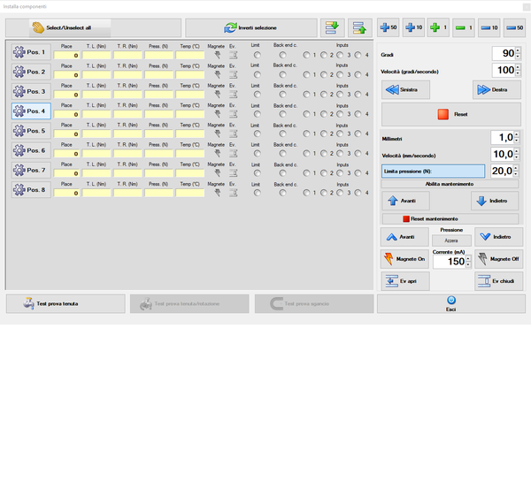
This feature allows the user to make axial movements or rotations during the installation of the components or during breaks of active testing. From this panel, you can also access another screen for manual execution of the leak test and others availables kind of test.
o access the panel select the menu Tools » Install Components or press F8; more simply press the next button in the toolbar:
On the left there are listed the places present in the system and for each of these are displayed the following information:
Position: position that is updated with each manual rotation performed;
T.L. (Nm): instantaneous values of torque during counterclockwise rotation;
T.R. (Nm): instantaneous values of torque during clockwise rotation;
Press. (N): axial pressure exerted on the component is available only if there is any axial movement, measured in Newton;
Temp (°C): temperature of the oven or of a possible additional thermocouple placed in the component itself, measured in ° C;
Magnet: icon light on or gray that indicates whether or not the passage of current for the simulation of heating of the thermocouple;
Ev: that indicate the state of electrovalve for air passage inside of the taps;
Limit: LED that turns red if the input hardware limit detects a twist exceeding 0.6 N;
Back Limit: LED that turns blue if the input hardware limit detects the hardware limit of the backward movement;
Inputs: LEDs corresponding to the inputs that are green if the contact is closed.
In order to rotate it is necessary to select a location by clicking with the mouse in the corresponding key. You can select all the places by pressing the mouse button Select all . Subsequently with the keys Left or Right you rotate with the degree and the speed set. The degree and the speed can be varied without the help of the keyboard using the buttons Up and Down:
Reset button performs the release of the motors while the keys Forward and Back respectively advance and retreat motors.
Other availables button for places selection are:
Rotation
It is possible to manually rotate the motor, counterclockwise or clockwise with an angle and with a rotation speed variables.
Degrees
The rotation can be from 1 to 360 degrees.
Speed degrees/second
Speed of rotation to do from 20 to 200 degrees per second.
Left
This command start the left rotation with degrees and speed specified.
Right
This command start the right rotation with the degrees and speed specified.
Reset
This command stops the movement and unlock the motors. (see section Options in chapter SETTINGS).
Axial movement
It is possible perform manually the axial movement of the motors to verify the correct positioning of the components.
Millimeter
Sets the length of the movement to perform for each command
Speed
Sets the speed (expressed in millimeters per second) to perform the axial movement
Limit pressure
If selected, set the maximum pressure beyond which the engine will no longer move
Enable maintain
If enabled, keeps the pressure as the set pressure
Forward
The command pushes forward The motors of the selected places.
Backward
The command moves back the motors of the selected places.
To return to the main application, press with the mouse, the button Exit.
Reset maintain
Cancels position retention
Reset/Restore pressure
For vertical test when a negative value is reads, equivalent to the weight of the motor, the operator has to press the Reset button to accept the value as “Zero”. This steps will avoid that the taps will be pressed with the motor weight plus the specified pressure limit. This option is saved also in configuration file and is automatically loaded at program startup.
To restore the normal mode for horizontal test, the operator has to press again same button identified as Restore.
The pressure labels will be showed in orange if the function is enabled.
Current to simulate the Thermocouple
To test the magnet operations, you can manually turn on and off the current in the magnets to simulate the heating of the thermocouple.
Magnet On
Enable the current in the selected components.
Magnet Off
Disable the current in the selected components.
Simulation of gas passage (with air)
To allow air to pass inside the tap during the test, it is possible to open or close the solenoid valve located at the inlet of each station. The air pressure will be the same of the outlet of the leakage test device and in any case not adjustable because it is shared between all the test stations.
Ev open
Opens the solenoid valve of one or more selected stations.
Ev close
Closes the solenoid valve of one or more selected stations.
Manual execution of Leakage tests
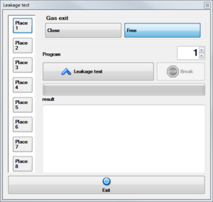
Press the button Leakage test to enter in the following panel:
With the buttons Free and Close in the test boxes Gas Exit it is possible open and close the shutter solenoid valve of the taps outputs, that normally at the beginning is open. To execute a test:
- select the position from 1 a 6 with the buttons on the left side;
- Than select the program to execute in the ATEQ from 1 to 4;
- Press the button Leakage test and wait the result in the text box RESULT.
Manual execution of leakage/rotation tests
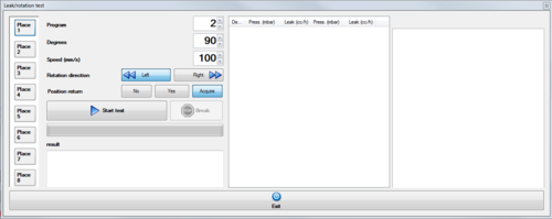
Press the button Leakage/rotation test to access the windows below:
In this window we can set program, degrees, speed, rotation direction, position return:
- Program : select the program to be executed by the leakage test machine ;
- Degrees : set the degrees to be performed for the test ;
- Speed : set the rotation speed for the test;
- Rotation direction : select the rotation direction L or R ;
- Position return : no , don't return to the starting position , yes , return to the starting position , acquisition , acquire data also during the return movimentation
In the end press the button Start test to begin the test. The acquired data will be displayed on the center screen, while the acquired charts will appear on the right screen. To exit, press the Exit button .
Manual execution magnet unlock test
Press the button Magnet unlock test to access the window below:
Before starting a test it is necessary to set this settings , program, max forward movement, max pressure movement, start current, current decrease, step current.
- Program : the program to run for leak tests in a static position , varies depending on the device installed
- Max forward movement : Sets the maximum movement you can make
- Max pressure movement : Sets the maximum possible pressure
- Start current : Initial hooking current set for the test
- Current decrease : Initial decrease of the hooking current
- Step current : decrease per second of the current
Finally, press the Start Test button to start the magnet unlock test for the selected position, on the screen below, the test progress will be displayed and Release (mA) will be the value obtained from the test. To exit, press the Exit button .
Manual execution of flow/rotation tests
Press the button Flow test to access the windows below:
In this window we can set program, degrees, speed, rotation direction, position return:
- Program : select the program to be executed by the flow test machine ;
- Degrees : set the degrees to be performed for the test ;
- Speed : set the rotation speed for the test;
- Rotation direction : select the rotation direction L or R ;
- Position return : no , don't return to the starting position , yes , return to the starting position , acquisition , acquire data also during the return movement
In the end press the button Start test to begin the test. The acquired data will be displayed on the center screen, while the acquired charts will appear on the right screen. To exit, press the Exit button .
Password
Some of the functions of database management and editing of parameters at startup , are password protected and you must enable them to take some sort of authentication by entering a password.
To enable the password-protected functions, proceed as follows:
- select Instruments→Password or press the following button in the toolbar:
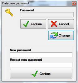
- insert the password in the windows and press the button Confirm.
To disable the functions (only if enabled):
- select Instruments→Password or press the following button in the toolbar:
To change the password :
- select Instruments→Password or press the following button in the toolbar:
- Then enter the password in the window that appears and press Change;
- Insert twice your new password in the appropriate text boxes displayed;
- Confirm the change with the key Confirm immediately below the boxes.
Backup complete
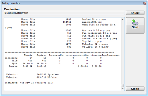
This function can be used each time it's necessary to create a complete backup of the application with all settings and data. Once selected the software shows the following panel:
The first time will be necessary to login with the password and will be possible to select the destination path. Other time if it's not necessary to modify the destination folder, each user can access to the panel to press the Start button to execute the copy.
/E all directories
/V detailed output
/NP no file progress
/R:3 retry 3 times
/W:10 wait 10 seconds
Optional files in the destination folder will not be deteled.
Setting
This chapter describes the interfaces of the operating modes of the system and the graphical display of data.
Graphic
To enter in the graphic setting select from the menu Setting » Graphic or push the key F10; or push the following key in the toolbar:
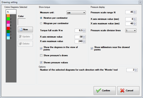
As a result you will see the following window
The panel is divided into three parts: the left panel Curve Colors Selected allows you to add, edit, and delete the colors of the selected curves; The center panel Torque display allows you to change the unit of measurement, display scales, to show degrees in point display, whether to display the pressure curves, and whether or not to display the pressure values and right panel Pressure display allows you to change the pressure unit of measurement, the display scales and whether to show or not show the millimeters on the pressure graph, and in the “options” below the panel you can set how many curves from Select when using the worst option.
To add a color in the selected diagram is necessary:
- Press with the mouse, the button New .
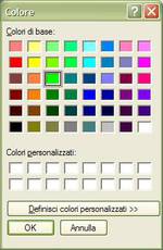
- Select with the mouse the button Color ; therefore, will appear the following figure:
- Choose a color with the mouse and press the button OK ;
- Press the button Update to save the data.
To change a color, you must:
- From the list select the color to change.
- Press with the mouse the button color .
- Choose a color with the mouse (see figure above) and press OK.
- Press Update to save the data.
To delete a color, you must:
- Select, from the list, the color to delete.
- Press with the mouse the button Delete and respond Yes in the next confirmation message.
To exit the window press the mouse button Confirm.
Options
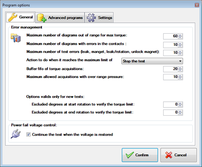
To enter in the managements of the options , select ftom the menu Program Options or push the key F11.
The windows is divided in two panels: General and Advanced program. The first panel contain the general options of application, the other one the basic options of the program running.
General
The options in this panel are for all tests regardless of the running program.
Fault detection
Maximum numbers of test out of maximum torque range
The user can set the maximum number of diagrams out of range, exceeding the torque, which are automatically saved during testing in addition to those planned. The achievement of the maximum number programmed can interrupt the test and wait or continue without the failed component.
Maximum number of curves with errors in contacts
The user can set the maximum number of diagrams with contacts errors, which are automatically saved during testing in addition to those planned. The achievement of the maximum number programmed can interrupt the test and wait or continue without the failed component. With the option Exclude detecting contact the program continues without count them.
Maximum number of error tests (leakage, magnet, leakage/rotation, release, flow)
The user can set the maximum number of tests for: leakage, magnet, leakage/rotation, release and flow with negative result. The achievement of the maximum number programmed can interrupt the test and wait or continue without the failed component. With some of the options described below, certain types of tests may be excluded, even if provided in the program.
Action when the maximum limit errors are reached
It indicates the action to take if a component reaches the maximum number of errors in the Torque or in the contacts detection:
- Stop testing: stop testing without any action;
- Stop place: interrupted testing of the tap in error and continues testing the remaining components;
- Exclude and continues: excludes the failed component (losing all data) and continues testing the remaining components.
Buffer fifo of torque acquisitions
Number of curves to be saved after an acquisition acquired for a torque value out of range.
Maximum number of curves with pressure error
The user can set the maximum number of tests for: leakage, magnet, leakage/rotation, release with negative result. The achievement of the maximum number programmed can interrupt the test and wait or continue without the failed component.
Valid option only for new tests
- Degrees excluded at the beginning of rotation, to verify the torque : sets the number of degrees to be excluded in the beginning of rotation , only for a new test
- Degrees excluded at the end of rotation, to verify the torque : sets the number of degrees to be excluded at the end of rotation , only for a new test
Check voltage absence
Continue the test when the voltage is restored
Your system, except the oven, is powered by an UPS. When the power fail , the system continue to work , until reach the first instruction of the cycle, (normally at the zero position) , stop the test and wait the power return. By selecting this option, the PC stops the test until the communication with the oven is in error.The program will wait for the power come back to resume the testing of components.
Advanced programs
Commands
Disable all the commands of the oven
This option allows to ignore all the commands of the oven, both setting (setpoint position airflap, ventilation) and the standby temperature.
Exclude waiting
With this option the program ignore all the waiting commands.
Turn on additional fan cooling with door open
If enabled, during the cooling phase, when the door is open, turn on the fan to speed up the cooling.
Turn on the extra heating resistor to reach the set point
If enabled during the phase of Heating , it turn on an extra resistor to reach faster the setpoint. Once the temperature is reached, the resistor is no longer used until the next command that set the oven temperature.
Exclude contact detection
Exclude contact detection during the test
Exclude leaking detection
Exclude leaking detection during the test
Exclude leaking/rotation detection
Exclude leaking/rotation detection during the test
Exclude magnet unlock detection
Exclude magnet unlock detection during the test
Exclude pressure detection
Exclude pressure detection at the end of rotation
Exclude flow/rotation test
Exclude flow/rotation detection during the test
Options
Flowing component rotation during leak/rotation and flow/rotation test
If selected, a flowing motor movement will be done during the leak/rotation and flow/rotation test and values reads at maximum speed ban be less then one for each degree, otherwise if the option is not selected the movement will be dove a steps of one degree and all the values will be reads.
Leakage test maximum time
Maximum time (timeout) for the leakage test.
Settings
View backup tool after test save process
If selected, at the end of the test, when the operator press the save button, the software shows also the backup panel from where the operator simply pressing the ok button activates the backup procedure in a different folder.
Oven Options
The working mode of the oven can be changed from a control panel in the main screen of the program.
The oven can works in two modes:Automatic and Manual. To select one or the other option , push the key Auto o Manual and answer Yes to the confirm message.
Automatic Mode
The oven temperature change in correspondence to the steps or the commands of the test programs.
Manual mode
The temperature and ventilation of the oven remain stable as values set manually by the operator during the execution of advanced programs, with commands that controls temperature and ventilation. Even the arm to open and to close the door, remains stationary in its current position. In this mode to change the temperature of the oven set the desired setpoint temperature and the gradient temperature in the fields and press the Confirm button . The same thing can be done to set the humidity
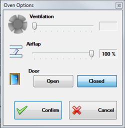
Manual Regulations
In manual mode, you can make the following adjustments:
- Ventilation;
- Nozzle cooling;
- Opening door.
To access the panel settings, press the corresponding button of the options and select the button Confirm to apply your changes or the Cancel button to exit.
Additional option for climatic chamber
If the system is equipped with a climatic chamber, in manual mode, it is necessary to put the device in the state of RUN in order to be able to adjust the temperature by pressing the button ![]() . The control can be interrupted by pressing
. The control can be interrupted by pressing ![]()
Exclude humidity control
Thehumidity control can be activate by pressing  and disabled by the same button when you see the icon
  .
.
Events
The program includes a register which stores any errors that may occur. Each fault is signaled to the operator by a message in which they are given an identification number and a brief description of the error. The same information is also stored in a register. Errors that occur during the execution of automatic procedures can not be communicated to the operator via message but are still stored in the registry.
View
To consult the Events list click with the mouse in the menu File » Events » View or push the button from the toolbar:
Il program display the following panel:
You can find three types of events according to their importance:
- Error
- Notice
- Information
Double-clicking on an event you can view the entire message in the event that the window is not wide enough.
Deleting
To clear the event log you must select the menu File » Events » Empty and answer Yes to the following confirm message.


